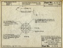
These are digitizations of original engineering drawings and other engineering data sheets (e.g., manufacturing operation sheets, bills of material, as well as an occasional item of special tooling) done by the Linotype Parts Company (later Star Parts) for their products compatible with Linotype or Intertype linecasters. These documents are especially significant because Star Parts reverse-engineered every part of a Linotype or Intertype that could wear out and then tested this work through decades of production. Their parts had an excellent reputation among independent Linotype and Intertype machinists.
Historians of linecasting and practical linecasters alike owe a great debt of gratitude to Dave and Beth Seat of Hot Metal Services for preserving these drawings and making them available. Were it not for their extraordinary efforts, all of these drawings would be decomposing in a landfill.
Plese note that this is a big project and that it is not yet finished.
Information for specific parts, by part number:
Information (including some engineering drawings) for parts, not associated with part numbers (or parts associated with a general kind of part, possibly over a specified range of part numbers):
Index, by drawing numbers only (not Operation Sheets, etc., which were not assigned drawing numbers).
See also the reprinted Mergenthaler Linotype Co. engineering drawings and the reprinted Mergenthaler Linotype Co. technical drawings for maintenance.
See also the "Individual Makers of Linotype & Intertype Compatible Parts" for modern reverse-engineered and/or compatible components.
The documents collected here bear upon everything an individual machinist might need to make a part. They do not include the documentation required to manage the production of a part, either in-house or outsourced. The general period of coverage begins just after World War II and goes to the early 1980s.
The organization here is by part numbers, not drawing or other document numbers. In the original paper versions, each type of document (drawing, operation sheet, bill of material, etc.) is filed separately in different filing cabinet drawers. Within each type of document the file folder organization in the drawers is by part number.
I have grouped all types of documents together here by part number. Thus, within each subdirectory in the presentation here the drawings, operation sheets, bills of material, and any other relevant data sheets are grouped together. Note that the revision levels of documents so juxtaposed may or may not be the same. Each item is identified by part number, drawing number (if a drawing), date, and name. (Most Star Parts operation sheets and bills of material were assigned "drawing" ("DWG") numbers.) But note also that LPC/Star was not consistent in the use of dashes in their part numbers on these documents.
When multiple revisions of the same part or drawing exist, or multiple retypings of the same operation sheet or bill of materials, all have been scanned. Copies of operation sheets annotated in production have been scanned; often these annotations are interesting.
Sometimes Star Parts part numbers for Linotype-compatible or Intertype-compatible parts are identical to the original Linotype or Intertype part numbers. Often, however, they are not. For example, a Star Parts A-38 is a 14-24 x 3/4 screw (with a single name) and a Mergenthaler Linotype A-38 is an identically dimensioned screw (which has at least 14 different names in late Blue Streak machines). But a Star Parts A-13 is a Matrix Hook while a Mergenthaler Linotype A-13 is a 1/2"-12 screw.
(For reference, Mergenthaler Linotype part numbers bear alphabetic prefixes from A through J [note to self: check to see if Comet or Elektron went futher]. US Intertype part numbers bear alphabetic prefixes from R through W (well, there was a single part prefixed 'FS'). When Intertype manufactured Linotype-compatible parts, they used their own part numbers.)
A single part, described by a single drawing, could of course be used in multiple places. (This is especially true of things such as pins and machine screws.) Typical Star practice was to assign a separate part number to each use, and note them all on the drawing. (This differed from Mergenthaler Linotype practice, where a single part with a single part number might be used under various names in various places.) Thus in Star practice p/n A-112 is also p/n M39C-E33 and both are described in drawing B-1903. Here I'll put the drawing itself under the first part number listed on it and refer back to it from entries for the other part numbers. Note that in both Star and Mergenthaler practice the name of the part might differ in its various uses. Names are merely functional descriptions. Only part numbers identify actual parts.
Perhaps because LPC/Star was making parts compatible with machines not of its own manufacture, certain apparent inconsistencies are present in its part numbering. Moreover, the documents present here do not represent the complete history of the Star drawing office. In particular, alphabetic suffixes do not necessarily imply later drawings. For example, p/n A-103, shown here in a drawing from 1947, was superseded by p/n A-103A, shown here in a drawing from 1946 (but this fact was not noted until 1951). The study of the Linotype is not simply a matter of engineering but also of archaeology and textual scholarship.
There are also inconsistencies which cannot be explained by oversights in revision but must have existed in the Star Parts inventory. For example, part A-26 is, simultaneously, a 1 1/4 inch long screw used for the Pot Pump Bracket and a 2 1/4 inch long screw used for the Cam Shaft Bracket. (Both are listed in the 1973 Star Parts catalog.)
In Star Parts' usage, a "Bill of Material" is a list of all of the components within a single part. It does not list the stock necessary to construct a part. A "Bill of Material" of this kind may seem trivial for a simple part such as, say, a brush with a handle, but it becomes increasingly important as parts become more complex.
Finally, note that this is a record of what has survived after much destruction. There are gaps which cannot now be filled and missing pieces which cannot now be recovered because the documents were destroyed.
I scanned these drawings at 600 dpi and saved the results, losslessly, as PNG images. These PNG images are rather large (typically just under 50 Megabytes each). At present they are too large to present online. For online presentation, I have converted each to a JPEG image at full resolution (600 dpi). These JPEG images are about 8 Megabytes each.
I have scanned and reprinted these in color, even though they are "black and white" line drawings and typescripts, because ink isn't really black and paper isn't really white. No monochrome image can represent the original well.
Most of the original sheets are ANSI A size drawings (that is, 8.5 x 11 inch (US "letter") size). Scanning them at 600dpi as done here results in images that typically are just over 7000 x 5000 pixels in size.
I experimented with adding thumbnail images of each drawing to the lists, but decided against doing so. Engineering drawings of parts reduced to inch-wide thumbnail images simply do not convey sufficient information to be useful in identification.
At the time of writing, many Web browsers do a poor job in allowing you to view images - you can either see it resized to fit the screen (perhaps too small) or full-size (showing only a tiny part of these 600dpi images). For best results, save these drawings to your own computing environment and view them there with a dedicated image viewer.
Please see the note on the copyright status of the Star Parts engineering drawings.
Circuitous Root is a Registered Trademark of David M. MacMillan and Rollande Krandall.
Presented originally by Circuitous Root®
Select Resolution: 0 [other resolutions temporarily disabled due to lack of disk space]