A pantograph is a system of mechanical linkages which reproduces the motion of one point of the linkage at a second point, usually at an increased or decreased size. It originated in the 17th century, and while its most familiar application has probably been as a mechanical drawing instrument, it appears throughout engineering. The so-called "parallel motion" of James Watt's steam engines, for example, employs a pantograph mechanism for the transmission of power and motion.
Here, in pretty much its simplest form, is the motion of a pantograph. [1]
Here is the first pantograph attested in the literature, from 1653. (Apparently angelic apprentices were easier to find in the 17th century than is the case today.) [2]
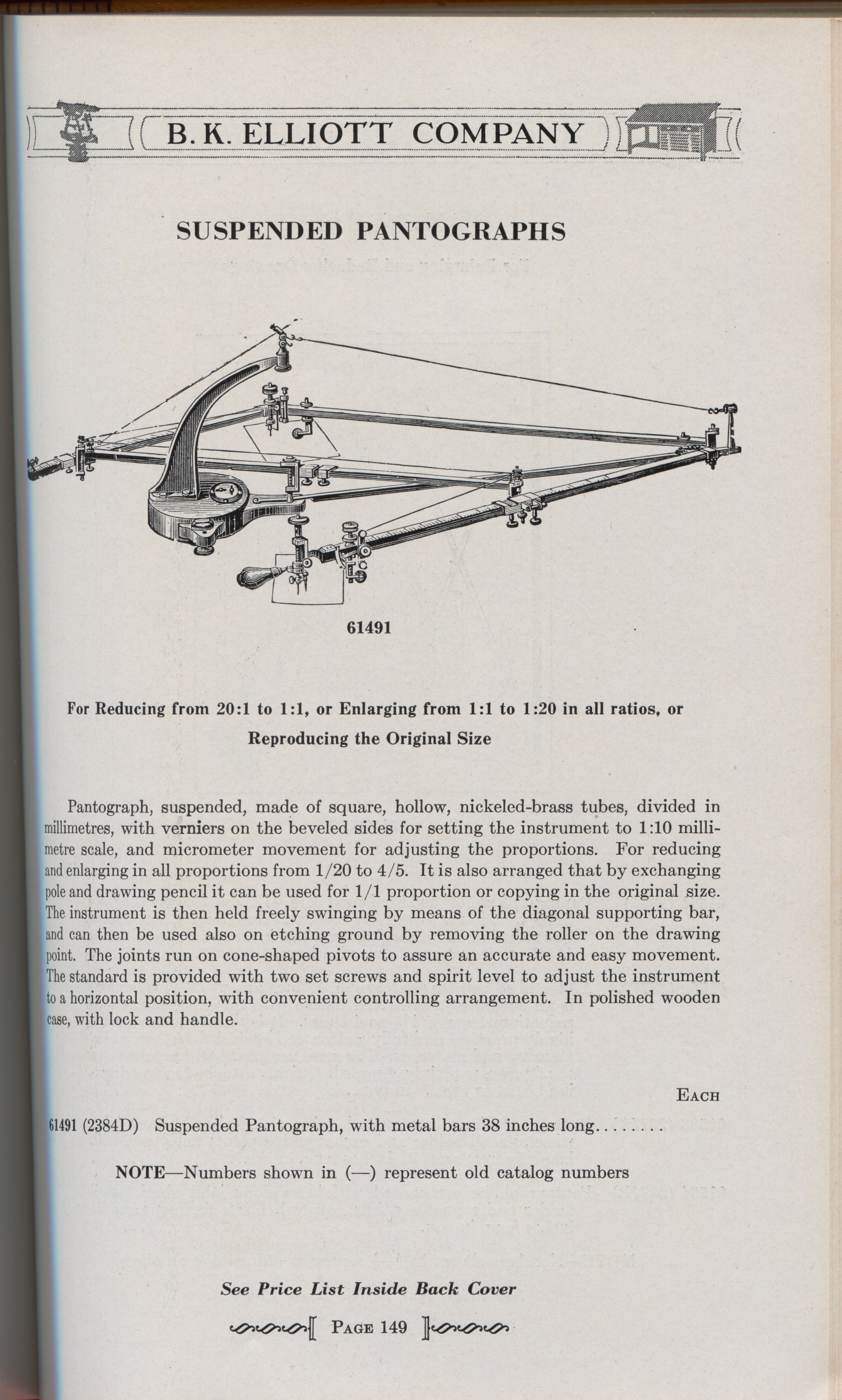
Here is a very nice 20th century drafting pantograph. [3]
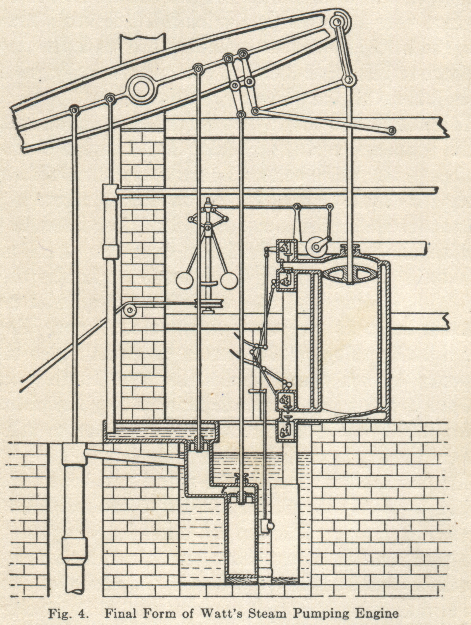
Here is an entirely different kind of pantograph - but still in every respect a true pantograph. It is the so-called "parallel motion" invented by James Watt to guide the piston and valve of his beam engines. In later practice, machined slideways would be used as guides, but the ability to machine sufficiently accurate slideways in sufficiently large sizes was not yet developed in the 18th century. The diagram on the right shows a portion of the motion of this device (if fully traced out it would make two "figure 8" paths). It is not a truly parallel motion, but it is more than sufficiently parallel for its purpose over a short range. [4]
(In a drafting or engraving pantograph, typically one point is fixed, one is guided, and the remaining point traces out a copy of the guided point. In Watt's pantograph, point A is fixed (enlarge the drawing on the right to see the identification of the points). Point "L and C" and point "B" are equivalent to the "guided" and "tracing" points of a regular pantograph. The motion of either point "L and C" or point "B" (take your pick) is constrained by an additional linkage "M - R" which causes one of them to generate the figure and the other to copy it at an enlarged (or reduced) size.)
Here's a different steam engine application. The motion of this engine are now guided by slideways (not a pantograph as in Watt's engine) but the engine has been instrumented with an "Indicator" - a device which records the pressure inside the steam cylinder at each point of the engine's operational cycle. In this application, the pantograph is an information-processing device which delivers a signal, at reduced amplitude, from the cross-head of the steam engine to control the motion of the Indicator. [5]
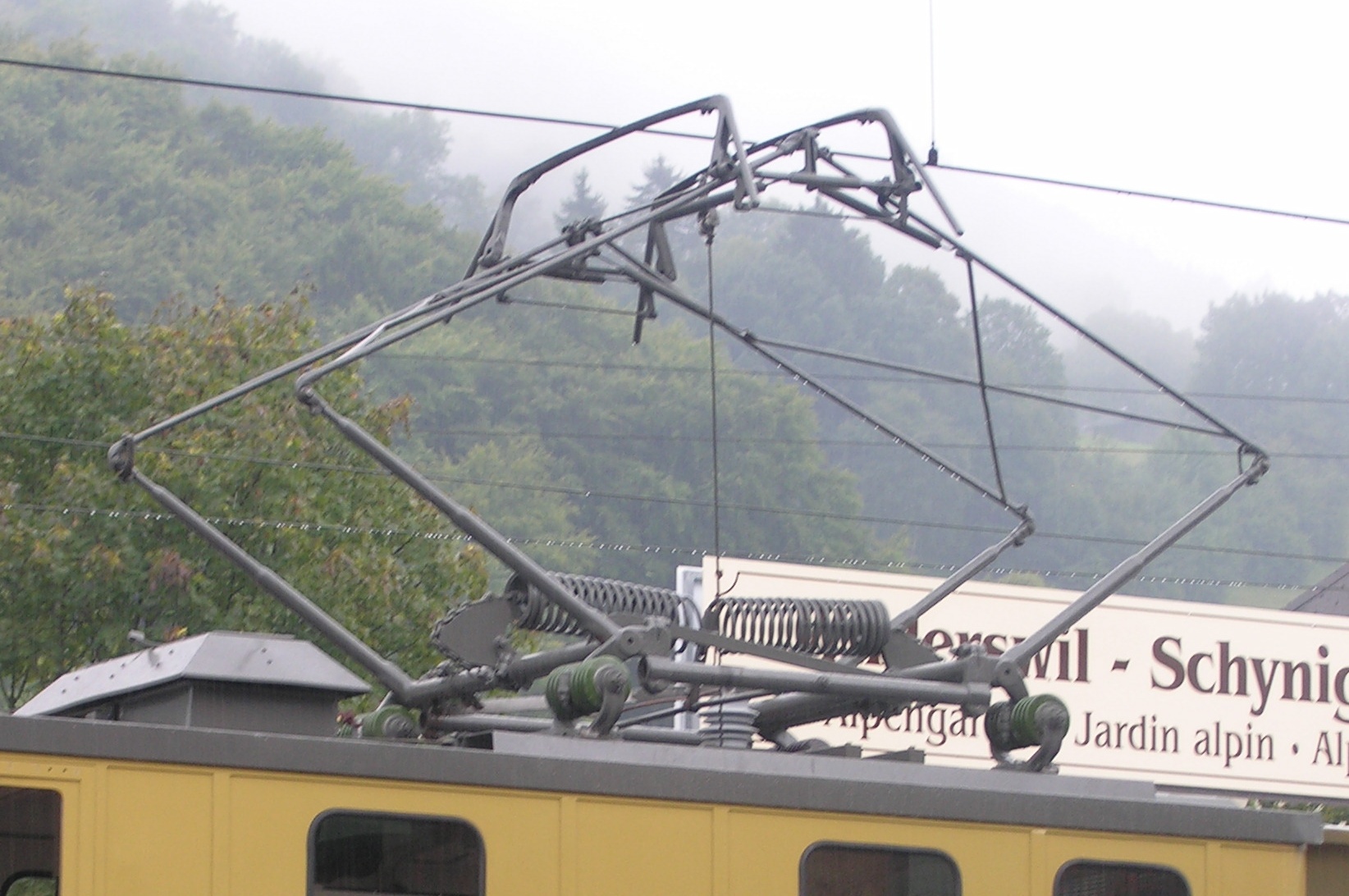
However, while pantographs vary widely in form and application, not everything which is called a pantograph really is a pantograph. The term was applied to the apparatus used to transmit electrical power from overhead lines to streetcars or railways. While it superficially resembles a pantograph, it does not scale motion in the ways done by the pantographs discussed above. Here's a photograph of a "pantograph" on a Swiss cogwheel railway [6]
A pantograph engraving machine, or pantograph engraver, is a pantograph which uses a cutting tool at one position on the pantograph's mechanism to engrave (cut) into a workpiece a design traced out by a tracer or stylus at another position on the mechanism. The cutting tool is most frequently either a sharp scribe fixed to the mechanism [7] or a rotary cutter. [8]
Pantograph engravers may be either "two-dimensional" or "three-dimensional."
In 2-D machines, the cutting tool moves in a plane, and the depth of the engraving is controlled by the depth setting of the cutter. This depth is commonly set up and held constant for any given engraving operation. Some 2-D engraving machines have attachments which allow 2-D engraving of contoured surfaces of 3-D workpieces, usually within relatively narrow limits. These options need not be considered here.
In 3-D machines, the tracing stylus and cutting tool both move in three dimensions within relatively wide limits. 3-D pantograph engravers were commonly used for the manufacture of stamping dies. When they operate at a scale of 1:1 they are often called "die sinking" machines. Various mechanisms were used for achieving 3-D capability; the "ratiobar" method of Gorton machines was particularly sophisticated. It is of course possible to do 2-D work on a 3-D machine.
Various mechanisms may be incorporated into either the pantograph linkage itself, or the tracer ("follower") and its tips, or both, to permit nonlinear scaling and (intentional) distortion of the pattern. This was particularly common in typographical work and in commercial lettering, but less common in industrial die-making.
All mechanical pantographs are presently obsolete for industrial work, having been superseded by computer-controlled milling machines. Their lack of appeal to accountants, however, does not make them any less useful to the artisan (or any less fun).
All of the pantograph engraving machines used historically for working pattern engraving were either 2-D drag or rotary engravers or (in at least one case) 3-D rotary engravers stripped of their 3-D apparatus and operated as 2-D machines.
All of the pantograph engraving machines used historically for matrix engraving were 2-D rotary engravers.
What follows here is a survey of several pantograph engraving machines, both those used for typographical work and those used in other kinds of work (e.g., lettering or die making). The purpose here is just to give a general feeling of the diversity of the field. Too often, works on matrix making have implied that there was only one kind of pantograph, or only one good kind. There are many. Almost all of them are good in one way or another, and many of them are good for the various stages of matrix making.
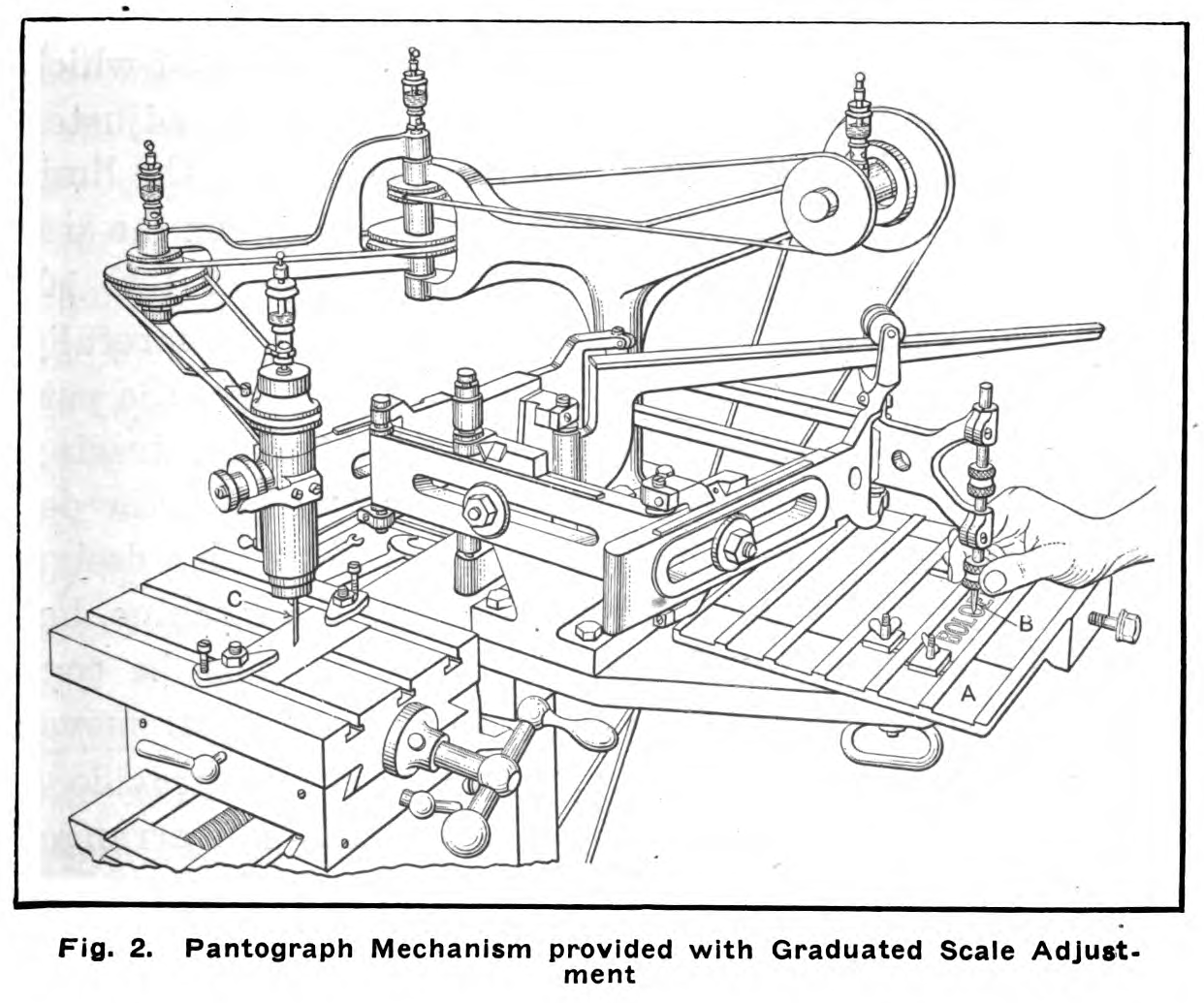
Here is a general view of an early 20th century industrial pantograph rotary engraving machine. It is possible that it does not represent any particular machine, since it is taken from a general book on the subject. It is a pretty straightforward implementation of the idea of the pantograph: there is a pantograph with adjustable linkages; it is anchored in its middle and has a tracer at one end and a cutter at the other. [9]
It is interesting to compare the pantograph above with those developed by the optical manufacturers Taylor, Taylor & Hobson and sold under the name "Taylor-Hobson." Here's an illustration of a fairly early Taylor-Hobson, from a trade note in an 1891 journal. [10] The digitization is a fairly muddy representation of what was once a good engraving, and the view from the side isn't as illuminating as it might be, but still it clearly shows a very different system of construction. The cutting spindle itself is mounted on a relatively heavy hinged arm. This arm is in turn guided by a much lighter pantograph mechanism above it.
The machine shown below is fairly lightweight in construction, but that is because it was intended originally for engraving information on lens mounts. Nothing in this method precludes heavier construction, and indeed separating cutting from control can in principle allow more effective heavy construction.
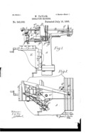
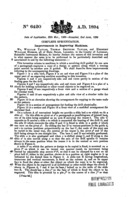
Here's the Taylor-Hobson mechanism as shown in the US version of William Taylor's 1894/1895 patent on the system. [11] Already the machine is depicted as much heavier - it could easily be confused with a Gorton or Deckel of 40 years later.
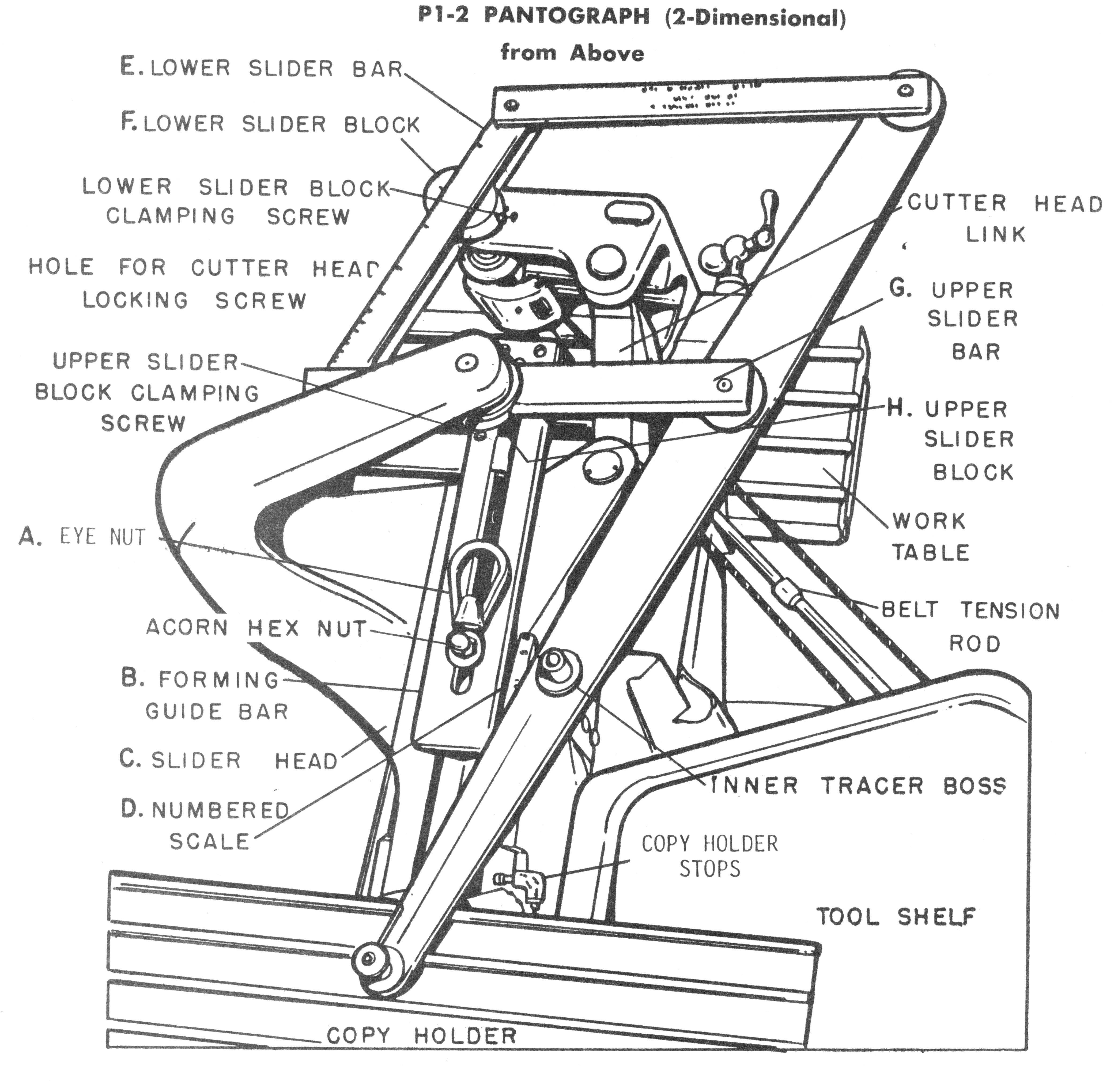
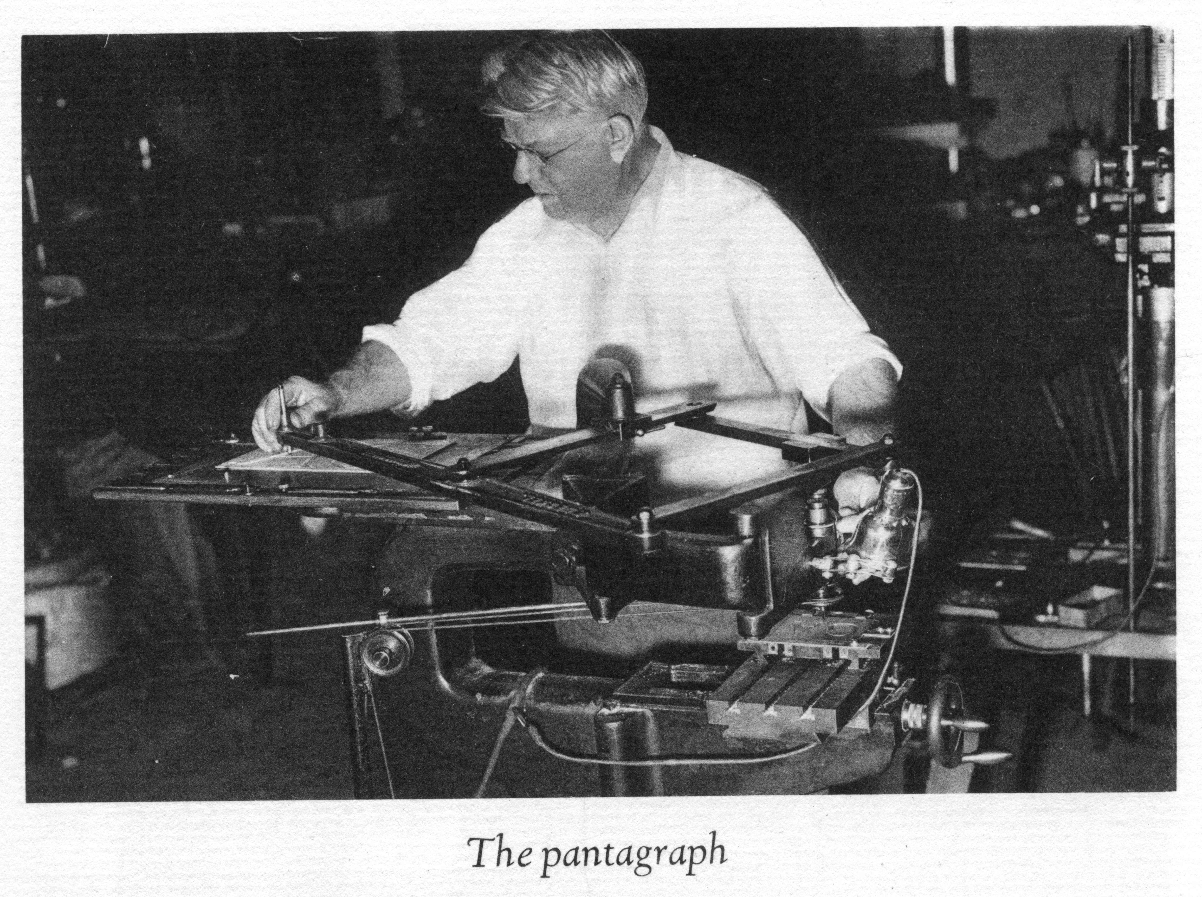
Gorton (of Racine, WI) licensed the Taylor-Hobson design and used its principles in many of their machines. Most of their 2-D machines, in particular, retained the distintive Taylor-Hobson look throughout their production history (and they remain nominally in production even today). Here are two views of a Gorton P1-2. This is a mid-sized, mid-century 2-D industrial pantograph; it replaced the earlier Gorton 3-U. [12]
Some Friedrich Deckel 2-D pantographs adopted the Taylor-Hobson principle as well. In particular, the Deckel machine used by Goudy in his Deepdene studio prior to 1939 was of this style. [13]
A wide variety of pantograph engravers were used industrially and commercially before the advent of CNC. A few are still available.
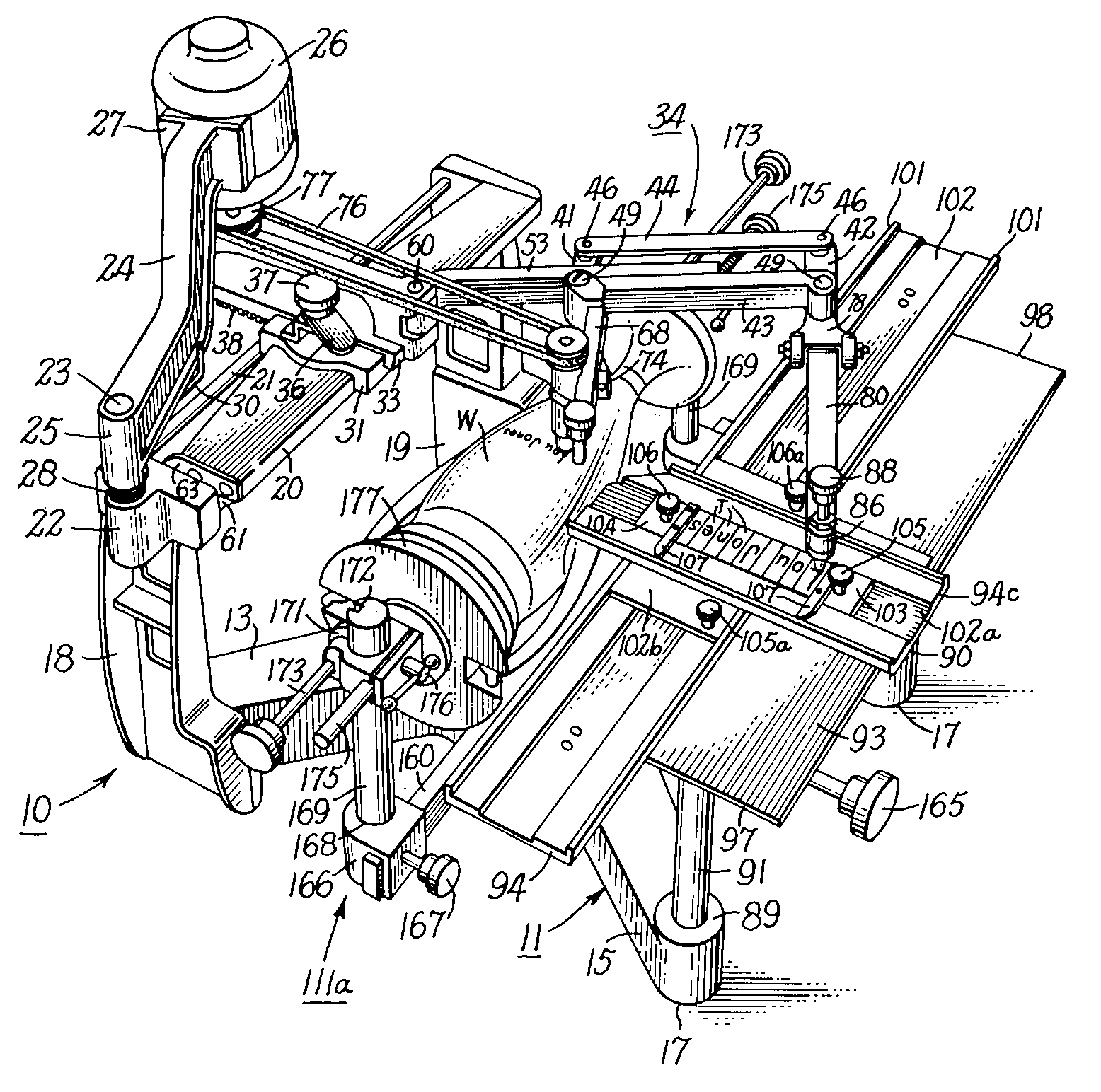
At the smaller end of the size range, the New Hermes (En)Gravograph machines dominated the market for engraving small signage, bowling tropies, and the like. They're fine little machines for their purposes (my wife uses them in her jewelry business). New Hermes began in 1938 with lightweight, fixed-ratio machines. These were developed by Gerhard G. Gruettner into the later variable-ratio models. There have been many models of New Hermes machines, but only two basic styles. In both styles the pantograph and the cutting mechanism are combined (rather than separate as in the Taylor-Hobson principle). In one style the pantograph mechanism is fixed in one horizontal position and the cutter is lowered via a micrometer mechanism. In the other style the entire pantograph mechanism is hinged at the rear of the machine and the cutting depth is regulated by a collar surrounding the cutting spindle. (New Hermes documentation is not always entirely clear about the differences between these two styles.) For a number of reasons, these machines would seem to be inappropriate for matrix engraving work (see Pantographs Not Suitable for further discussion). They might have some application in engraving working patterns, but their ratios are limited when compared to industrial machines such as the Gortons. Here is a mid-century New Hermes, from a patent illustration. [14]
Even smaller pantographs are made for portable applications (and one could also remove the pantograph mechanism from some New Hermes models and apply it directly to the workpiece). Here is a small portable pantograph used to guide an engraver for lettering identifying information on a bicycle frame. [15]
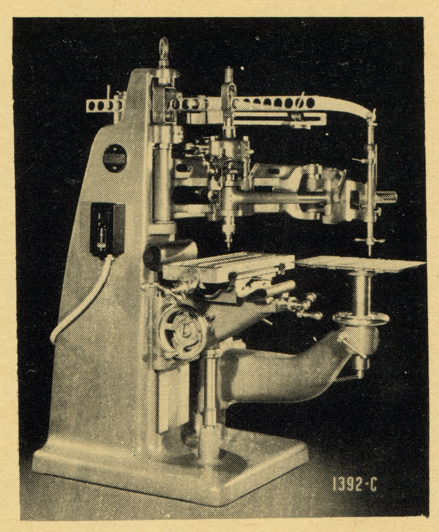
At nearly [16] the other end of the size range, Gorton made a range of heavy industrial pantographs such as the model 3-L shown here from a 1950 catalog. [17] The 3-L was succeeded by the P2-3 when Gorton later re-engineered their line and rationalized their product designations.
Those familiar with Benton's well-known pantographs for patrix, punch, and matrix engraving no doubt will have noticed that the pantographs shown above don't look at all like Benton's. Benton's vertical style pantographs are examples of another class of machine entirely. They've frequently (but not always) been called "pantographs," but I don't know any accepted name for this class of device. Here I'll make up a name and call them "single-arm" pantographs.
These trace their historical origins to an entirely different source: the "ornamental turning" of the early modern period, and more specifically to the medal or medallion copying lathes which were developed as one small branch of that marvelous field. (I would guess, though, that although a number of "single-arm" pantographs come directly out of this tradition, the machines of Benton and of Hollerith, discussed below, were independent re-inventions.)
The field which is now generally called "ornamental turning" has a rich, complicated history (and is at present experiencing a vigorous revival). Put most simply, it is the modification of the lathe and the application of any number of often exceedingly clever mechanical contrivances to the lathe (and sometimes to other machines, such as "straight-line engines") to produce by entirely mechanical means work which a 21st century viewer would swear must have been done on a computer-controlled machine. Most of this field, while fascinating, is not relevant to the present discussion. See the CircuitousRoot Notebooks on Ornamental Turning for more information.
One of the more specialized subdivisions of this field is that of the "medallion" or "portrait" lathe. This is a copying machine tool adapted to reproduce low-relief portraits or designs of the type one might find on a medal. In the 18th century, a period of wars and rising empires as much as enlightenment, this was an important capability. It is obviously useful to be able to enlarge or reduce the workpiece from the pattern, and one method by which this is achieved is a "single-arm" device that we might now call a species of pantograph.
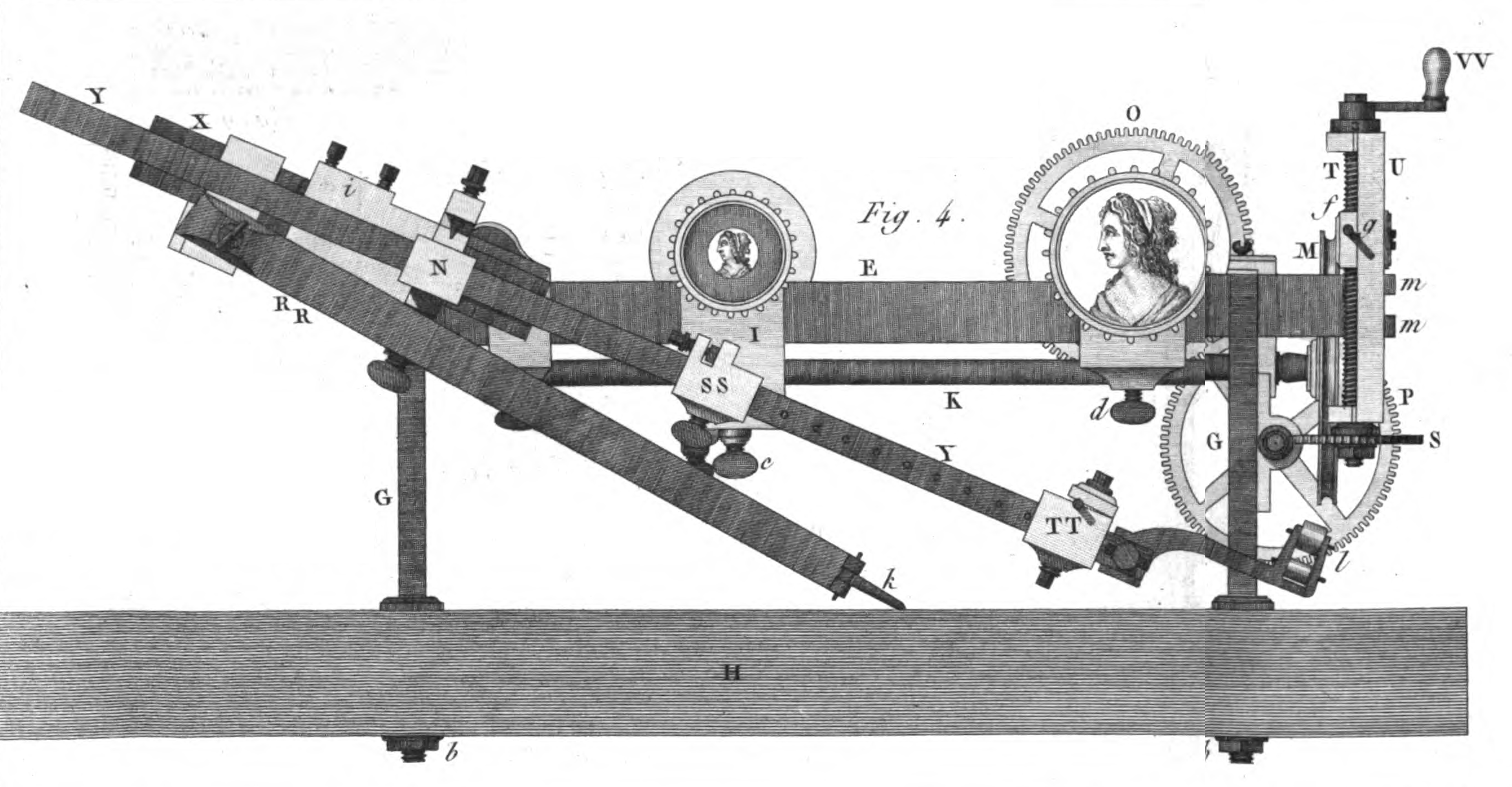
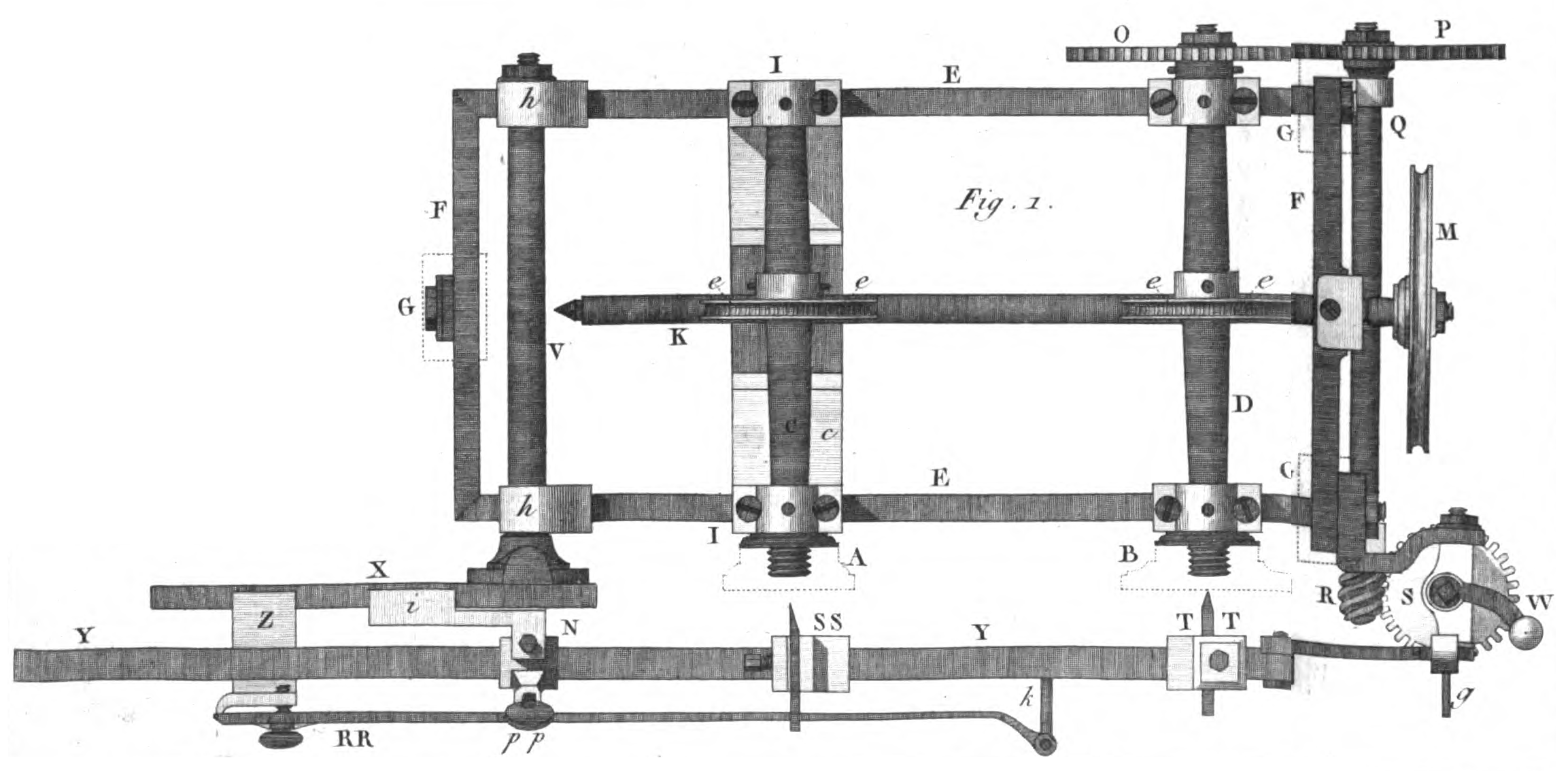
Here is an example of one such machine, taken from an influential late 18th century book on turning published under the name of "Bergeon."
(See [footnote 18] for a discussion of the sources of and issues with these images.)
It is actuall a double lathe, mounting the pattern and the workpiece on separate headstocks facing the front of the machine. The tracing and cutting tools are mounted on an arm pivoted at the left.
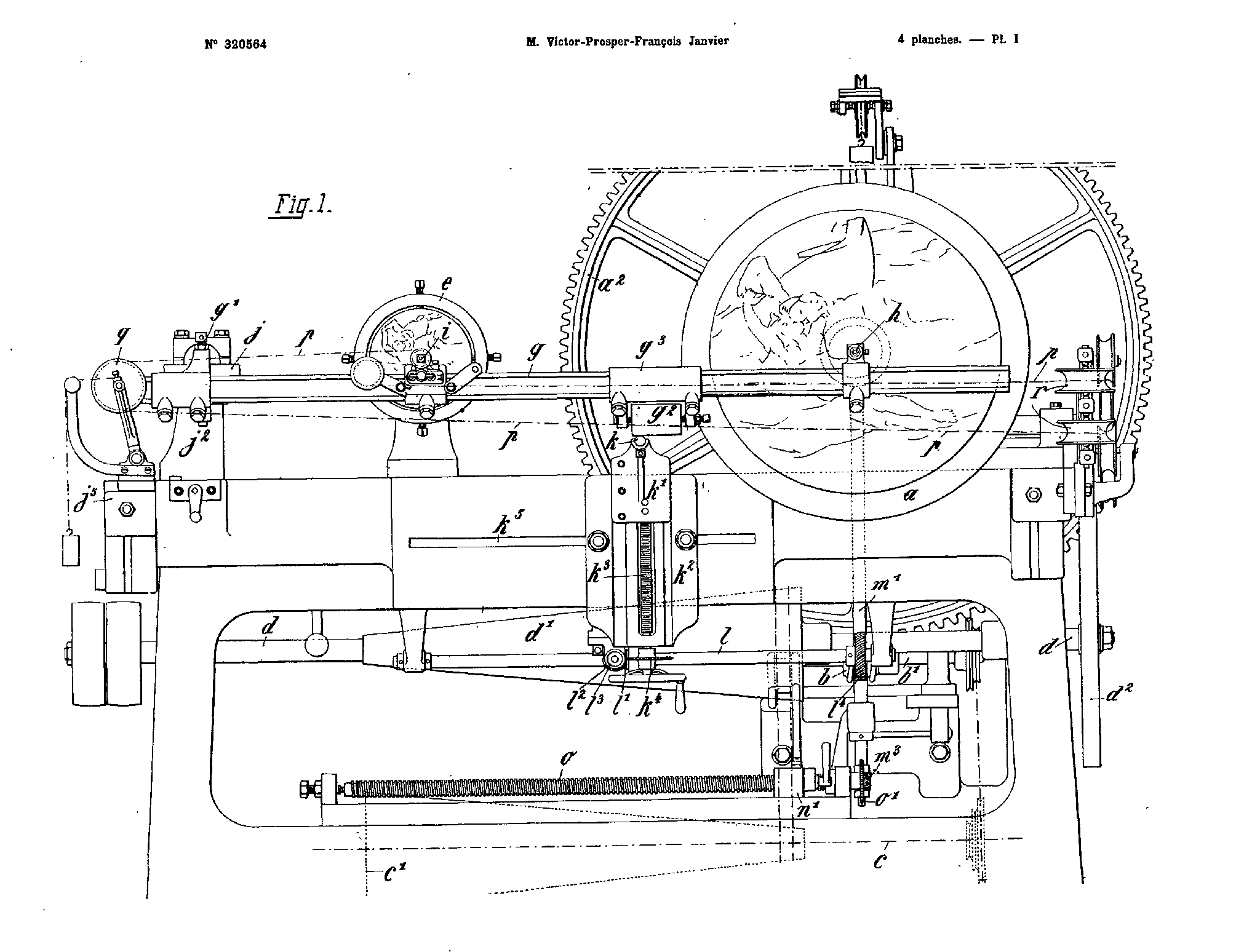
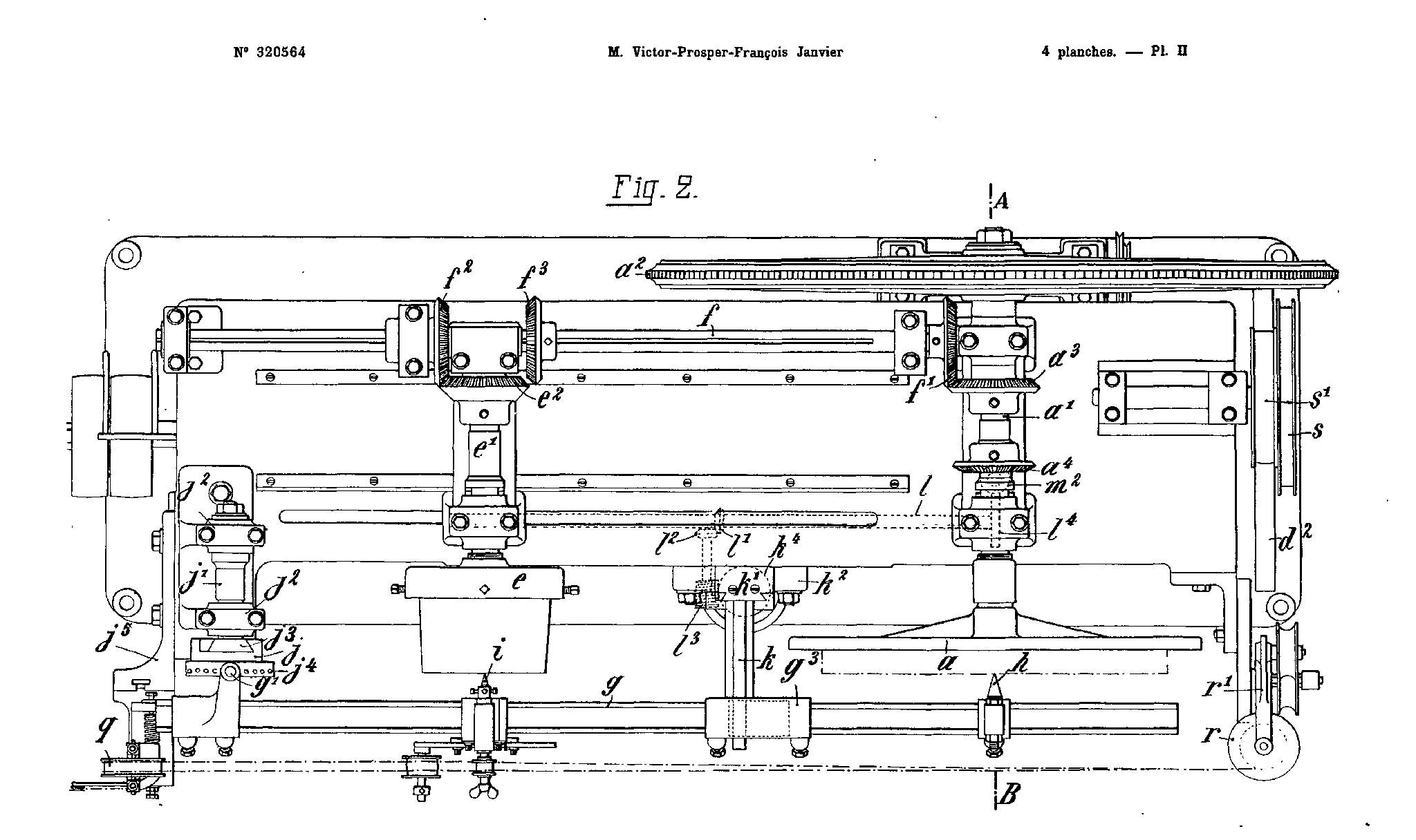
Skipping forward many years [19], in the 1890s and early 20th century, Victor-Prosper-François Janvier, in France, developed various improved versions of the basic medallion lathe for use in cutting ("sinking") dies for striking coins and medals. Here's a view of one, taken from French patent No. 320,564, issued 1902-04-21 to Janvier. Its relationship to the machine shown in Bergeron is clear.
Janvier die sinking machines were used in mints and in industry throughout the 20th century, and a few continue in service in the 21st. It is sometimes called a pantograph, and sometimes not. [20] See the CircuitousRoot Notebook on the Janvier Machine for more information. [LINK BROKEN - I haven't written that Notebook yet]
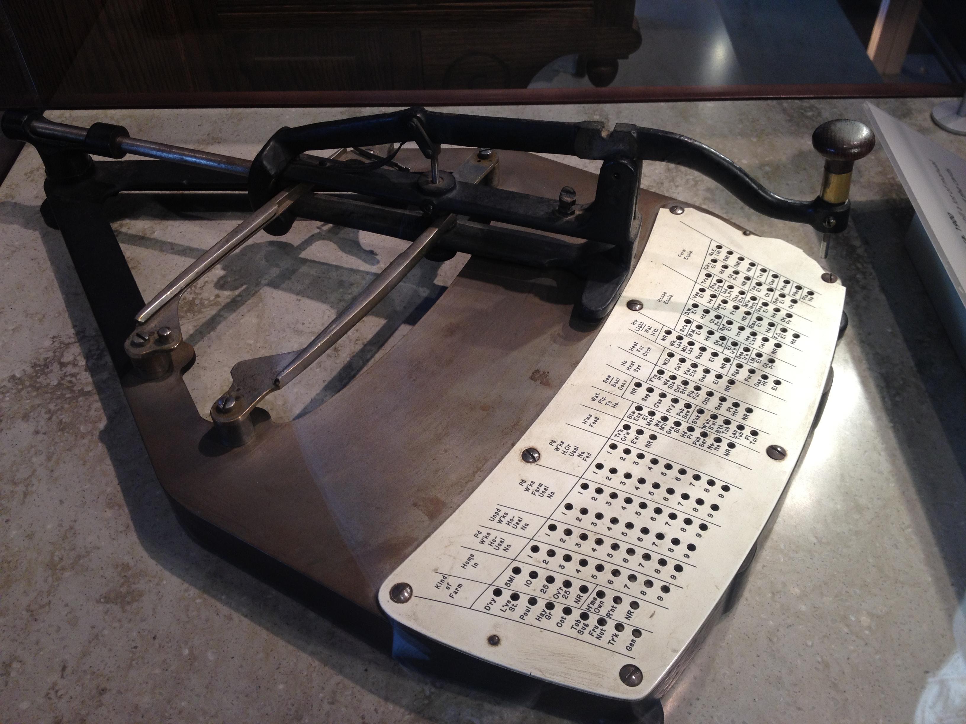
A short time before Janvier's die sinking pantographs, Herman Hollerith developed a pantograph for use in his tabulating equipment. (The patent for it was filed in 1891, but while it was designed to use the 1890 census card, I do not yet know if it was in fact used in the 1890 census.) It is also a "single-arm pantograph," and it was termed a pantograph at the time.
Here's a photograph of a Hollerith Pantograph Card Punch at the Computer History Museum [21]
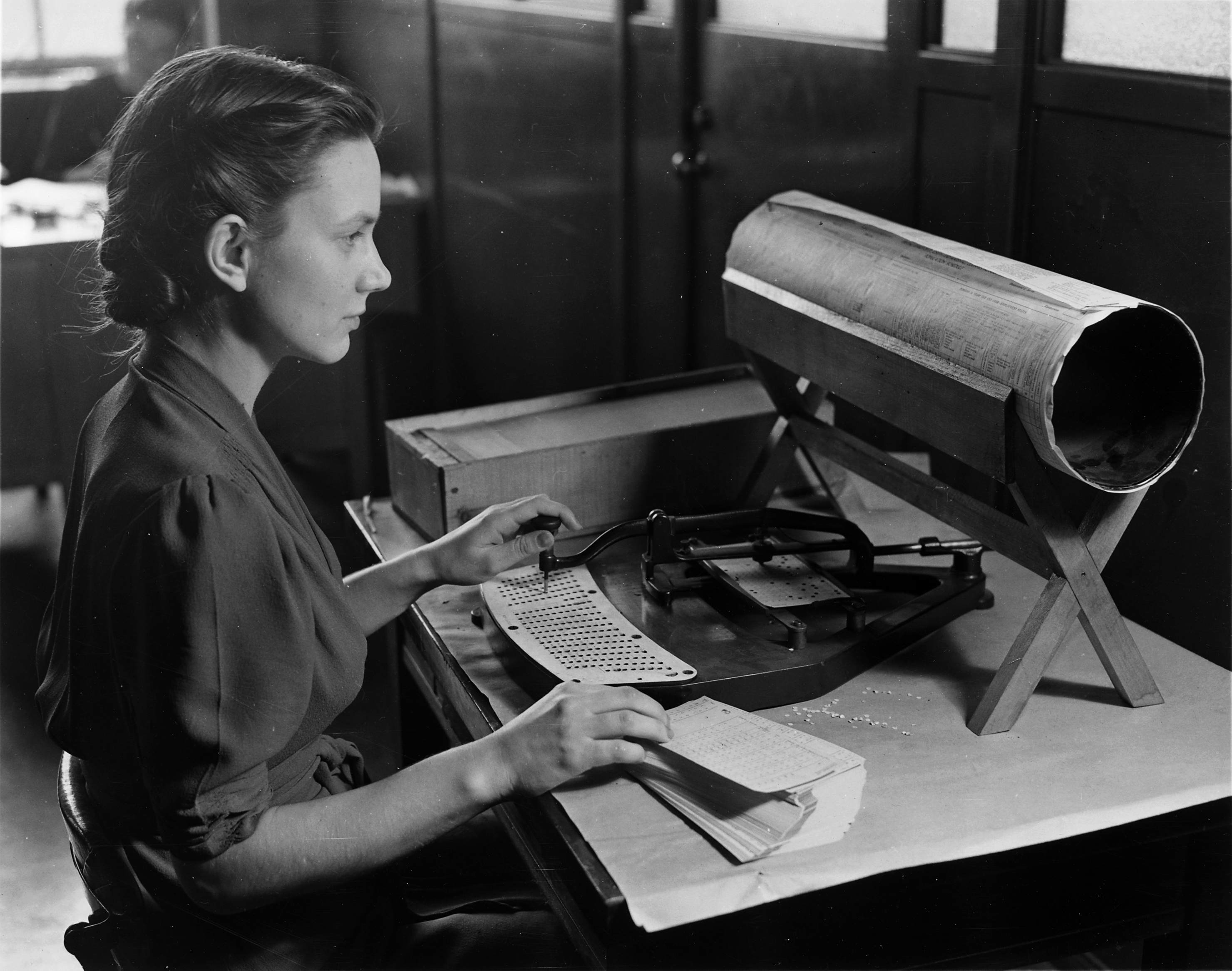
Here a punch is shown in use, in a US Bureau of the Census photograph. [22]
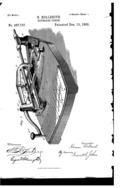
US Patent 487,737 (1892)
US patent 487,737, "Keyboard-Punch." Issued 1892-12-13 to Herman Hollerith. Filed 1891-03-10 as application serial number 384,498. Not assigned.
The Hollerith pantograph makes quite obvious a point about "single-arm" pantographs that is not commonly articulated in the typographical community [23]: that this type of pantograph necessarily introduces some distortion. The curves in two dimensions in the hole-plate of the Hollerith pantograph are necessary to produce a regular rectangular grid of punches on the card itself.
The horizontally oriented single-arm pantographs noted above all swing their arm on a pivot. In the Bergeron and Janvier machines, it can swing up and down, primarily in a single plane. In the Hollerith machine, it can swing left to right (again, primarily in a single plane). The working planes of the machine are parallel to the plane defined by the swing of the arm. (There is some motion in the third dimension, but it is relatively small and only present to allow the tracer and tool to follow low-relief contours. The same kind of small motion in a perpendicular dimension is possible, for example, in the nominaly 2-D Gorton 3-U and P1-2 engravers to allow engraving on curved surfaces. In computer graphics terminology, this are more like "2 1/2 dimensional" machines.)
It is also possible to arrange the arm so that (a) it is suspended vertically, and (b) it swings on a universal joint or gimbal. When this is done, the working planes of the machine are horizontal, at right angles to the rest position of the arm.
The best-known machines of this type were of course those of Linn Boyd Benton. By 1884, he was advertising the capability to cut typographical punches in steel by machine. (It isn't certain when he began work on this machine; 1883 is a good bet. It is likely that the very first versions of the machine performed the very similar operation of engraving patrices in typemetal.) He filed for a patent on a vertical-format single-arm pantograph in 1885. Fifteen years later, in 1899, he patented a kinematic inversion of this pantograph adapted for cutting typefounding matrices directly.
[TO DO: Illustrate Engle/Eaton/etc. machines; may be Francis machine. Illustrate Benton 1885 (punch/patrix) and 1899 (matrix) machines. Illustrate late Eaton machine used by Goudy.]
A number of pantographs have been developed specifically for work in the various stages of making type. For these see:
But note that in a number of cases standard commercial machines, sometimes stock and sometimes modified, have been used successfully.
1. An animation by user "AlphaZeta" from Wikimedia Commons: http://commons.wikimedia.org/wiki/File:Pantograph_animation.gif
2. From Scheiner, Christoph. Prattica del parallelogrammo da disegnare. (Bologna: Giacomo Monti, 1653), p. 21. Digitized by the Getty Research Institute and presented on The Internet Archive ( www.archive.org).
3. From Catalog and Price List, Sixth Edition, (Cleveland, OH: B.K.Elliott Co., by 1942), p. 149. Scanned by DMM from the original.
4. The drawing on the left is from Ludy, Llewellyn V. Steam Engines. (Chicago: American Technical Socity, 1920), p. 6. Scanned by DMM from the original. The drawing on the right is by DMM.
5. From Hawkins' Indicator Catechism. (NY: Theo. Audel & Co., 1901.); composite of figures on pp. 32 & 33.
6. This is a photograph by Wikimedia Commons user Audrius Meskauskas (Audriusa): http://commons.wikimedia.org/wiki/File:Schynige_Platte_diamond_pantograph.jpg It shows a pantograph on a "Swiss-made locomotive from [the cogwheel] Schynige Platte mountain railway."
7. One example of the use of a scribe, from practice which is still current, is the "diamond drag" method of using the New Hermes "[En]gravograph" machines. The Monotype Corporation (UK), and probably also American Type Founders in Benton's early methods, used a pantograph with a scribe to cut away a wax plate for the electroforming of working patterns.
8. Other cutting methods have been used. The Gorton Company at one point made an electric-arc etching head for their pantograph machines. There have been a very few attempts to make pantograph engraving machines which used a single-point directional cutting tool guided in imitation of hand engraving (vs. a scribe, which is an omnidirectional tool). The Francis machine and one variation of early [Eaton-]Engle machines used this method. No such machine achieved any commercial success, however. None of these alternative methods will be discussed in this present book.
9. From Graduating, Engraving, and Etching. First Edition. (NY: The Industrial Press, 1921), p. 31. Digitized from the Columbia University copy and presented at The Hathi Trust (www.hathitrust.org).
10. From The Telegraphic Journal and Electrical Review. Vol. 28, Whole No. 700, April 24, 1891. (London: H. Alabaster, Gatehouse & Co., 1891): 530. Digitized by Google from the NY Public Library copy and available via the Hathi Trust (Hathi ID: nyp.33433062756634)
11. US patent 542,902, "Engraving Machine." Issued 1895-07-16 to William Taylor, a citizen of England. Filed 1894-05-28 as application serial no. 512,790. Below are PDFs of this US patent (from USPTO scans, assembled into a PDF by DMM) and its original English version (No. 6,420 of March 30, 1894, from the European Patent Office espacenet web service). The equivalent German patent was issued 1894-04-08 as No. 80,915; I have not yet obtained a copy of it.
12. From US Army technical manual TM 9-3417-218-14&P (1984).
13. From Lewis, Bernard. Behind the Type: The Life Story of Frederic W. Goudy. Pittsburgh, PA: Department of Printing, Carnegie Institute of Technology, 1941.
14. US patent 2,729,892, 1956-01-10. To Gerhard. G. Gruettner.
15. This is a photograph by German Wikipedia user Pfaerrich, who has placed it in the public domain. See http://commons.wikimedia.org/wiki/File:KIRBA-Pantograph.JPG The original caption reads "Gravurgerät der Firma Kirschbaum (Kirba). Der im Schablonenhalter gesteckte Code wird im Storchenschnabelverfahren verkleinert auf das Sattelrohr eingraviert und anschließend die Gravur mit einer Schutzfolie vor Korrosion geschützt." The photograph was taken in 2004 and uploaded to the German Wikipedia in 2006.
16. Nearly, but not quite. If you look through early Gorton literature, they made some truly enormous engraving machines in the heroic era of American engineering. The Gorton No. 1-M Universal Engraving Machine shown in their 1925 catalog, for example, stood 12 feet high and weighted 18,000 pounds. It was used for engraving lettering on the molds for rubber tires up to 42 inches in diameter.
17. From Gorton Pantograph Instruction Book and Parts Catalog, Form 1385-E. (Racine, WI: Goerge Gorton Machine Co., 1950). Scanned by DMM from the copy that came with my P1-2.
18. The bibliography of "Bergeron" is complex. See the CircuitousRoot Notebook on "Bergeron" for more information. The two images above come from the Google Books scan of the University of Ghent copy of the 1816 edition of the volume of Plates, Atlas du Tourneur. It would be polite to call this scan inept. The images above have been assembled (by me, fairly crudely) from images extracted from this scan. You really want to buy the printed edition of Volume II (in two volumes, text and plates) edited by Jeremy Soulsby in 2010. In it, the plates are well reproduced.
19. In particular, it's worth taking a look at the little known sub-field of "brocade engines." These are like medallion lathes, but in addition to copying they also impart to the cutting tool a patterned motion such that it can cut a texture while simultaneously copying the basic pattern. See the Brocade Engine and Medallion Lathe section of the CircuitousRoot "General Descriptions and Basic Sources" about Ornamental Turning Notebook .
20. A 2013 posting to the Briar Press online letterpress printing community (thread: http://www.briarpress.org/33454) indicated that the Janvier machine on display at the Casa de la Moneda (the Mint Museum) in Madrid, Spain, bears the description "Pantógrapho para grabado" (pantograph for engraving) on its placard.
21. Photograph by Arnold Reinhold. From Wikimedia Commons, at http://commons.wikimedia.org/wiki/File:Hollerith_card_punch.agr.JPG, where its author has licensed it for re-use under the Creative Commons Attribution-ShareAlike 3.0 Unported license.
22. The photograph of a Hollerith punch in use is by the Public Information Office of the US Bureau of the Census, US Department of Commerce. It is presently located at the US National Archives and Record Administration, Still Pictures Records Section, Special Media Archives Services Division and is cataloged under the National Archives Identifier ("ARC Identifier") 513295. It was shared by the US National Archives with Wikimedia Commons, and is available at: http://commons.wikimedia.org/wiki/File:This_is_a_card_puncher,_an_integral_part_of_the_tabulation_system_used_by_the_United_States_Census_Bureau_to_compile..._-_NARA_-_513295.tif
23. Although Nicholas J. Werner, in comparing the horizontal-format pantographs used in St. Louis since 1882 to the vertical-format pantographs developed by Benton from at least 1884 does make this point: "The upright pantograph, however, produces a certain small amount of distortion of the pattern used, due to swings from a central point, where the flat pantograph has no distortion." ( "An Address" (1931) / "St. Louis in Type-Founding History" (1941)).
Wikimedia Commons user AlphaZeta has released their pantograph animation GIF into the public domain. As reproduced here it remains in the public domain.
Christoph Scheiner's Prattica del parallelogrammo da disegnare. (1653) and its digitization by the Getty Research Institute presented on The Internet Archive are in the public domain. The reprint of the material from it here remains in the public domain.
The B.K.Elliott catalog, 6th edition, is in the public domain. The digitizations from it by DMM reprinted here remain in the public domain.
Llewellyn Ludy's Steam Engines is in the public domain. The digitizations from it by DMM reprinted here remain in the public domain.
Hawkins Indicator Catechism is in the public domain. The digitizations from it by DMM reprinted here remain in the public domain.
The photograph of a railway pantograph by Andrius Meskauskas has been licensed by him under the Creative Commons Attribution-ShareAlike 3.0 Unported license. Its use here is under the terms of this license, and any further use of it must also be under the terms of this license.
Graduating, Engraving, and Etching. is in the public domain, as is its digitization presented at The Hathi Trust. The reprint of the material from it here remains in the public domain.
The Telegraphic Journal and Electrical Review Vol. 28 is in the public domain, as is its digitization presented at The Hathi Trust. The reprint of the material from it here remains in the public domain.
US patent documents are in the public domain by law. The reprints of them here remain in the public domain.
Taylor's 1894 GB patent was subject to Crown Copyright, but that has expired and it is in the public domain. The reprint of it here remains in the public domain.
Lewis' Behind the Type is in the public domain. The digitization from it by DMM reprinted here remains in the public domain.
The photograph by German Wikipedia user Pfaerrich was placed by them in the public domain. As used here it remains in the public domain.
The 1950 Gorton Pantograph Instruction Book and Parts Catalog is in the public domain. The digitizations from it by DMM reprinted here remain in the public domain.
The photograph by Arnold Reinhold of a Hollerith Pantograph is licensed by him under the terms of the Creative Commons Attribution-ShareAlike 3.0 Unported license.
The photograph of a Hollerith Pantograph in use by the US Bureau of the Census is a US federal government photograph and therefore in the public domain by law.
All portions of this document not noted otherwise are Copyright © 2012-2013 by David M. MacMillan and Rollande Krandall.
Circuitous Root is a Registered Trademark of David M. MacMillan and Rollande Krandall.
This work is licensed under the Creative Commons "Attribution - ShareAlike" license. See http://creativecommons.org/licenses/by-sa/3.0/ for its terms.
Presented originally by Circuitous Root®
Select Resolution: 0 [other resolutions temporarily disabled due to lack of disk space]


