These projects are also case studies in my general attempts at the Reverse Engineering of Big Old Machines (though they're relatively small by comparison to, say, a Barth Type Caster).
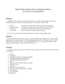
Parts Symboling Scheme
An attempt to establish a rational parts symboling scheme which will be useful across a range of plain and lever hand molds in the three major styles of construction.
I wrote this up as a LibreOffice / Apache OpenOffice document, so as to make it easier to print a shop copy. The icon at left links to a PDF version. Here's the original document: hand-mold-parts-symboling-scheme.odt
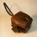
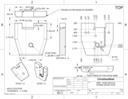
HMA: A 19th Century Lever Hand Mold
Photographs and measured drawings (not engineering drawings) of a 19th century lever hand mold. Pica body. Probably of American origin. "Composite" style of construction.
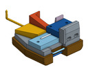
HMB: A Newly Drawn Plain Hand Mold
A newly drawn, but "generic" and of traditional construction, non-lever hand mold. For use with a traditional hand mold style of matrix. Depth of Drive: 0.050. American/English nick position. 24 point body. "Composite" style of construction.
All portions of this document not noted otherwise are Copyright © 2015-2016, 2023 by David M. MacMillan
Circuitous Root is a Registered Trademark of David M. MacMillan.
This work is licensed under the Creative Commons "Attribution - ShareAlike" license, version 4.0 International. See http://creativecommons.org/licenses/by-sa/4.0/ for its terms.
Presented originally by Circuitous Root®