This Notebook deals with the internal construction of the Gamet Dual Dial Cartridge installed on the Top Slide of my Clausing-Colchester 13" (= Colchester Master 2500) lathe (p/n 87476-0). For the overall screw and handwheel assembly into which this Cartridge fits, see Driving the Top-Slide Leadscrew .
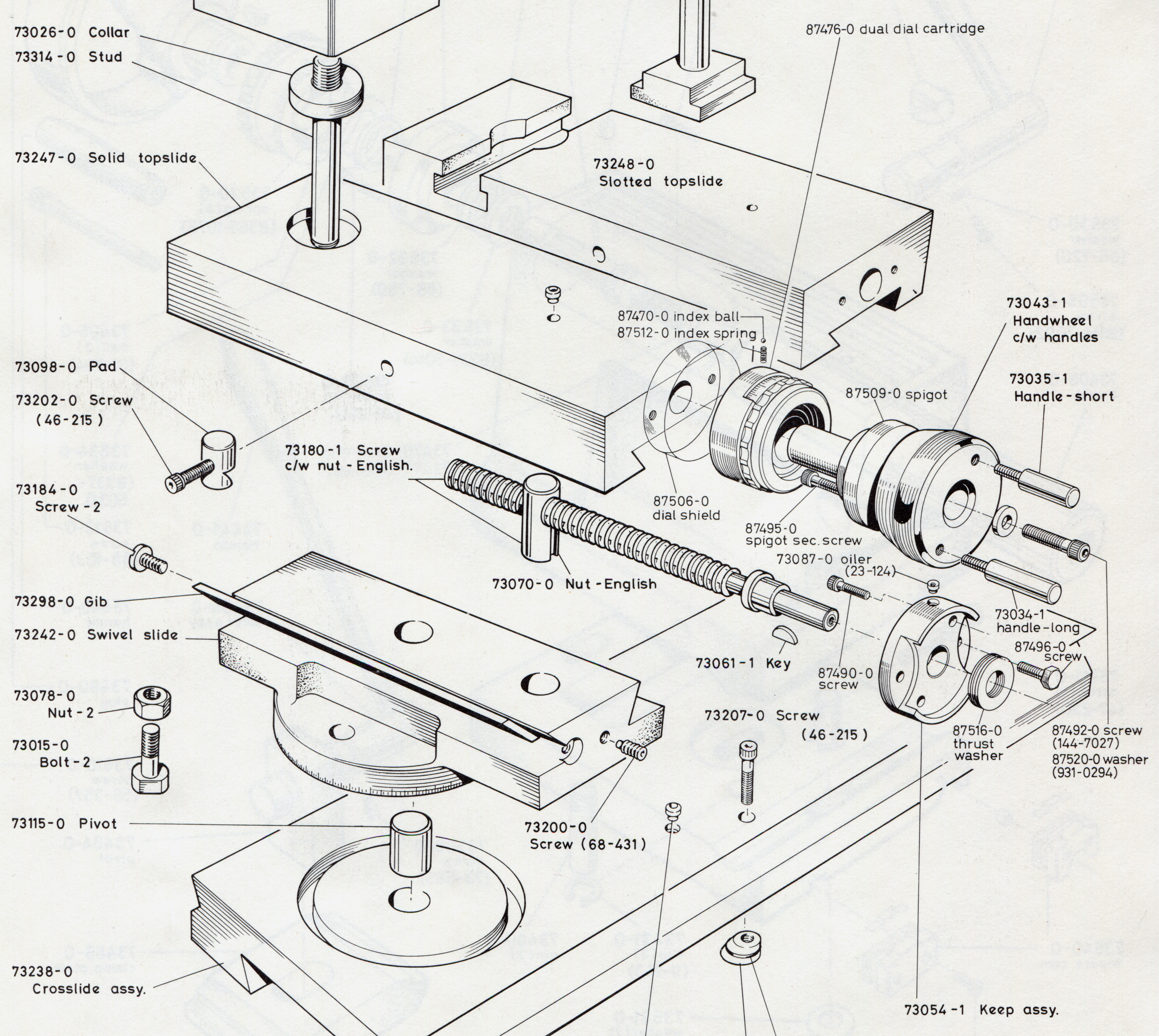
Here is the Dual Dial Cartridge as identified in the parts book:
These dials were made by what is now Gamet Products Ltd., a specialized bearing manufacturer based in Colchester, England and a unit of The 600 Group. The 600 Group also owns the Colchster Lathe brand. They owned Colchester when my lathe was made; I'm not sure if they owned Gamet then or not. The markings on the dials of my lathe, "GMT," suggest that perhaps at that time the company might have been "Gamet Machine Tools" - but I'm just guessing at this.
Gamet held at least three English patents for dual-reading dials. The mechanisms described by each of these three patents (GB 1,193,831, Sindall; GB 1,264,994, Waplington; GB 1,463,732, Hill) are in each case quite different. The dial considered here is based on the third of these patents, GB 1,463,732 filed in 1974 (issued 1977) by Stanley Hill.
See Differences Between Models and Over Time for a note on the differences between the Dial described here and the one described in the Colchester dual-dial fitting instructions.
The computation being done mechanically, by gears, within the Dial employs two gears, one of 125 teeth for the metric scale and another of 127 teeth for the inch scale. The reason this works is described in GB 1,193,831 (all three Gamet patents use similar internal gear mathematics) for a case of an 0.2 pitch leadscrew. I'll extrapolate that discussion here to the 0.1 inch pitch feedscrew of the Top Slide.
A single rotation of the handwheel moves this 0.1 inch pitch feedscrew 0.1 inches, regardless of what the dials might show. If the dial simply had the metric reading engraved directly on it, it would show a movement of 2.54 mm per rotation. What we want, though, is an indication of 2.5. So if we make a metric scale that reads 0 to 2.5 mm, we must gear it so that it actually travels 2.54 mm per revolution. In other words, the (dimensionless) ratio between the inch-reading scale and the mm-reading scale must be 2.54/2.5 = 1.016. It turns out that 127/125 = 1.016, exactly, so an inch scale attached to an inch gear of 127 teeth and a metric scale attached to a metric gear of 125 teeth will do the trick. Neat.
I know of no parts list or manual for this Dual Dial Cartridge, so I'll just have to make up names for the parts. Often, I'll follow the nomenclature of the patent.
The core of the Dual Dial Cartridge is what I'll call the "Block." (In the patent, its functions are performed by two pieces, the End Block and the Intermediate Block.) This is a relatively complex, though substantial, piece which performs several (passive, but important) functions.
Here it is, all by its lonesome:

Actually, it's not entirely alone. As shown above, it has installed on it the 28 tooth Pinion which will mesh with both of the "computational" scale gears. This Pinion is on a short shaft which appears to be driven in to the Block. It revolves freely on its own axis, and is held captive in this position. In operation, the whole Block and the area around the Pinion especially is packed with a Molybenum Disulfide grease (mostly removed here in a vain attempt to keep my camera clean). There was no need to remove this Pinion when I disassembled my Dial Cartridge, so I didn't.
The number of teeth on this Pinion doesn't matter, so long as it's a number reasonable for meshing with 125 and 127 tooth gears. It's just an idler, and doesn't factor in to the mathematics of the gearing.
The first point to be made about the Block is that it is fixed rigidly to the Keep Assembly. Since the Keep Assembly is, in turn, fixed rigidly to the Tops Slide, so also is the Block. Below, it is shown first with the Keep Assembly, and then with the screws in the Keep Assembly (two hex-head screws which fasten the Keep Assembly to the Top Slide, and two socket-head cap screws which fasten the Block to the Keep Assembly).


Here it is fromthe "Top Slide end," not yet tightened up:

But assembling it in this way is a bit artificial. The Block has other jobs to do, and other components need to be fitted to it before it is attached to the Keep Assembly. You would never reassemble to the state shown above in normal servicing.
One other job the Block does is to provide radial positioning for the "Keep Assembly Inside Bearing" (q.v.), also known from the parts list as p/n 87512-0, Thrust Washer.

As noted in the Driving the Top-Slide Feedscrew Notebook, (a) these bearings are described as a "Thrust Washer" in the parts list, not as bearings, and (b) on my lathe they were obviously misassembled; I have no idea now whether their assembly is symmetric or not.
They just fit snugly, but freely, into the recess in the Block. In use, the Spigot will push them up against the Keep Assembly, so don't worry about that.

This next bit is the part most likely to surprise the unwary mechanic. The Block houses two spring-loaded ball bearing Detents which hold the rotatable Sleeve in one of two positions (showing inch or showing metric). If you just pull the Sleeve off, the springs will launch these tiny ball bearings to unknown destinations in the shop. Much colorful language and crawling around on under the bench with a flashlight will ensue.
First, let's take a look at the Sleeve. It is a part of the Dual Dial Cartridge, but it just slides over the inside end of the Cartridge and, once you remove the Cartridge as such you could just slide it off. Here it is positioned between the Keep Assembly and the Block:

Here's how it fits onto the Block, and how the Keep Assembly retains it in place. The Keep Assembly and Block are fixed to the Top Slide, but the Sleeve may be rotated freely.


Now before showing the Detents, let's get a little bit ahead of things here and show what it is that the Sleeve does.
Within the section of the Sleeve which has the "metric" opening we'll be installing a ring Dial with metric graduations:


Under the rest of the Sleeve (the part with the "inch" opening) we'll be installing another ring Dial, this one with (of course) inch graduations. It's a slightly more complex piece, because it has a ridged section to allow the operator to turn it manually to zero-set the dials.

It takes up the rest of the space under the Sleeve, with the ridged section projecting beyond the Sleeve:


(In the photos above, the parts are just loosely placed together, not properly assembled.)
Getting back to those spring-loaded ball Detents, here is a photograph, with a close-up, that I took while disassembling the Dial Cartridge. I took it just after I slipped the Sleeve off, little thinking that it had spring loaded parts inside. You can see the small hole in the Sleeve into which one of the two Detents slips when it engages. You can see the spring which has just launched the ball Detent. This one launched its Detent at me; I could feel it bounce off my vest (tiny as it was), but of course had no idea where in the shop it finally landed. There is a second, similar, arrangement on the opposite side. I got lucky with it - I could hear it bounce off a small metal dish on the bench, and it stayed on the bench.


Here's a view of one of the Detents (the one I finally found on the floor, under the workbench) and its Spring. In case you should happen to lose both ball Detents, they appear to be steel ball bearings and their diameter is 0.094 inches (which is nearly 3/32 inch).

I'm not entirely sure what the best disassembly procedure might be so as to avoid this problem. One possible solution might be to take the entire Dial Cartridge, once removed, and to seal it in a large freezer-size zip-seal plastic bag. Zip-seal the bag. Then pull the Sleeve off while the whole unit is contained in the bag. I haven't tried this yet, but it might work.
As far as reassembly is concerned, I think I've figured out a method. See Tiny Spring-Loaded Ball Detents in the Disassembly and Reassembly Notes.
Finally, now, we can get on to some actual graduated dials! The Block holds both of them.
The first of them is a metric dial. It is aluminum, with engraved numbers anodized red, and an annular internal gear made of steel.


The red surface isn't a separate piece; it's just an anodized surface of the aluminum dial. I don't know how the steel gear is affixed. It's probably just a press fit, as there is no sign of any pin. I didn't have to take it apart, so I didn't.
The dial is graduated from 0 to 2.5 millimeters. The direction of positive rotation is clockwise. When turning the handle clockwise, you're moving the Top Slide " in," which is the normal direction for increasing graduations. (I must be slightly dyslexic, because I have to re-think this one every time. The Top Slide feed Screw goes through a Nut on the Swivel Slide. When you're turning clockwise, you're "tightening" the feed Screw. This is going to pull the Dial toward the Nut, which in turn will move the whole Top Slide in the "in" direction (which is usually into the work, depending on the work setup.))

This metric dial just slips on to the Block, red side in first. Its internal gear teeth mesh with one half of the idler Pinion. It is a very close fit; if you skew it at all when assembling it, it will jam. But once on, and firm up against the Block with no skew, it should be an easy rotational fit.


Functionally, the metric dial does nothing but turn under the control of the idler Pinion. It is always engaged with the idler Pinion, and however the Pinion turns, so also the metric scale turns. It is an entirely dependent calculating assembly. (If you think about this like a computer programmer, the metric dial is a bit like a subroutine.)

The Inch Dial is considerably more complicated, mostly because it must accomodate a mechanism for zero-setting.
The Inch Dial itself is semi-permanently assembled into a subassembly which consists of three components (and a hollow locating/retaining pin). Here it is assembled:


(In the image above right, it is being propped up on a piece of letterpress printing type for the photograph; ignore the piece of type.)
As a complete subassembly, this unit just slips on to the Block. Its internal ring gear (to be discussed) meshes with the other half of the idler Pinion, linking the two gears (and dials) together as a self-contained inch-metric calculating machine. It is probably a good idea to line up the zero points on both dials when installing the Inch Dial Subassembly, although, to be honest, I have not worked out the logic of whether or not it matters when zero-setting the dials after many revolutions.

When assembled as shown above, the two Dials are linked together and turn in a fixed inch/metric conversion ratio relative to each other. Taken together, though, they both can turn independently of the Block (which is fixed) and any other part of the apparatus. The rotation of the threadded part on the right, which is as yet independent of the dials, will be discussed below.
The Inch Dial Subassembly consists of three major pieces, shown disassembled below. These are: (1) A 127 tooth internal ring gear (steel). (2) The graduated Dial itself (aluminum) with engraved, anodized graduations and an integral ridged section for turning by hand.' (3) A "ring" with a collar on one end, threading on the other end, and a slot cut in the threads. The equivalent part in the patent is just called a "ring." I'll be a bit more explicit and call it the "Dial Driving Ring," because that's what it does.

As was apparent in the photos above, the 127 tooth ring gear fits into a recess in the aluminum Inch Dial. It is a press fit into the dial. Additionally, it is partly retained and partly keyed to a hollow Pin driven into the Inch Dial. I think that this helps to ensure that the gear's teeth line up correctly with the dial so that it may be set to match the zero on the Metric Dial (which, however, has no such pin).


The Inch Dial itself is pretty self-explanatory (by now, at least). It is graduated from 0 to 0.1 inches, in units of 0.001. The direction of positive rotation is clockwise, which is the same as the Metric Dial. (They can rotate in the same direction because they don't mesh directly with each other, but mesh via an idler Pinion.) The ridged portion is used to turn it to zero-set either of the Dials.
The "Dial Driving Ring" is a bit more complicated, and it took me a while to understand it. It is held captive by its collar within the assembled Inch Dial Subassembly (held in on one side by the Inch Gear, and on the other side by a shoulder within the Inch Dial. So assembled, it simply rotates freely within the Inch Dial Subassembly. It is the main component of a mechanism which allows the Dials to be either fixed to the rotation of the Handwheel (thus indicating motion) or free to rotate on their own (thus allowing zero-setting). I'll discuss this below, after finishing up with the Inch Dial Subassembly as a whole.
This present section is probably redundant, as it shows something you'd never see when assembling the Dial. As I already had disassembled the Inch Dial Subassembly, I took some photographs of what its gear would look like meshing with the Pinion, without the rest of the Inch Dial obscuring it. As can be seen below, this gear "sits" (abuts against) the previously-assembled Metric Dial. It rotates clear of the Block (its radial alignment will be determined by the bore of the Inch Block, and it meshes with half of the the idler Pinion.


The Inch Dial Subassembly is held on by a large-diameter threaded nut or ring which screws into the threads on the end of the Block. (The patent used a different method, an retaining it by means of an "abutment member" which was in turn secured by bolts.) I need a name for it, so I'll call it the Inch Dial Nut.
Here (repeated from above) is the Block (with the Metric Dial fitted). The threaded portion of the block used for retaining the Inch Dial Subassembly is on the right.
Here is the Inch Dial Nut. You can see the two holes in it by which a two-pin spanner might be used to remove it. (I didn't have an appropriate one, but was able to unscrew it anyway.)

Because the "Dial Driving Ring" (as I'm calling it) projects so far out beyond the end of the Block, the Inch Dial Nut is buried fairly deeply within its bore (no doubt this is why it is provided with holes for a two-pin spanner). It's hard, therefore, to get a good picture of it installed. Here is a picture with the Inch Dial Subassembly set in place (not quite all the way, if you look closely) and the Inch Dial Nut in place on the Block, ready to be screwed in.

There is one more detail involved in the Inch Dial Nut. It isn't just screwed in, but is retained with a set screw. No doubt this is because you can't just screw it in tightly - that would keep the Dials from moving, and they must be able to move. There are two issues, however, with this set screw.
The first problem (as I see it) is that this set screw pushes up against the threads of the Block. I don't think that mashing threads with a set screw is anyone's idea of good engineering.
You can see the hole in the Block where this set screw goes in this image (copied from above); the hole is threaded, though the threads aren't apparent in this photo.
It just screws outward, into the threads of the Inch Dial Nut. Here's a close-up of the threads of the Nut; you can see the damage from the set screw:

The second issue is the identification of the set screw itself. I have measured its thread very carefully, with a good Starrett thread gauge under a 10x loupe. If it is an inch thread, then it is a 50 tpi thread (48 tpi is too coarse, 52 tpi is too fine). It measures 0.113 inches in actual external diameter. The problem is that according to both Machinery's Handbook (25th edition) and my older 7th edition of Colvin and Stanley (often more useful), such a thread does not exist. It isn't UNC or UNF, or UNEF or a watchmaker's thread. It isn't even Whitworth or BA.
If it is a metric screw, it is possibly (or at least nearly) 0.5 mm pitch. It measures 2.87mm in actual external diameter. This suggests that it might be an M3. But comparison to an actual M3 indicates that it is not - almost, but not quite. (But an M3 screw may, with slight persuasion, be induced to fit the hole sufficiently well for use.)
Finally, the hex socket of this screw measures 0.058 (or possibly a hair more) between flats. It fits well on a 1.5 mm hex wrench, but an 0.050 inch hex wrench won't work.
So I have no idea what this nonstandard or at least no-longer standard screw actually is. This suggests that it would be a good idea not to lose it.
The Dial Driving Ring is a part of the Inch Dial Subassembly, but really merits a section on its own. It is the means by which the Dials are either keyed to the Handwheel for use or left to rotate freely for zero-setting.
Here it is again. Note now especially the slot cut through its threaded portion.
When the Dual Dial Cartridge assembly as a whole is installed, this slot engages with a tooth or stud in the Spigot and is thus keyed at all times to the Spigot (and thus the Handwheel and the Top Slide feed Screw). So the Dial Driving Ring partakes of the motion of the Handle.
Here it is by itself, alongside the Spigot.

Here it is fitted to the Spigot. This is a view you'd never see in actual reassembly, because the Dial Driving Ring is always captive inside the Inch Dial Subassembly. Still, it shows the driving key quite clearly. Note also that the Key does not fill the slot. That extra space in the slot will be used for something else.

Here it is as above, but now captive within the Inch Dial Subassembly.

At this point, the whole Dual Dial Cartrige looks something like this:

(In the photo above, the parts are just loosely fitted together. In actual assembly, the two Dials would be tight against each other and the Inch Gear would not be visible betwen them as it is here.)
But as shown above the Dials are not driven when the Handwheel is turned. They are free to rotate or be rotated by themselves. This is what you want for zeroing them out, but for use there must be some way of engaging them.
This function is accomplished by a combination of a special keyed spring-washer and a large diameter nut. In the patent, this Nut is called a "Lock Nut," but the mechanism as implemented here differs from that of the patent. I'll call it an Engaging Nut, because it is used to engage the Dials.
Here are the parts: (left) Keyed Spring Washer, (middle) protective flat washer, and (right) Engaging Nut.

The "Keyed Spring Washer" has two distinctive features. First, although it's hard to see in the pictures here, it is dished. This makes it a sort of a Belleville washer, although it's much thinner and more ring-like than a traditional Belleville washer. Second, it has a tab or key. This fits into the slot on the Dial Driving Ring and keys the movement of the Washer to the Ring.


This Keyed Spring Washer simply slips over the Dial Driving Ring and rests against the aluminum Inch Dial. Its key or tab goes in the slot, as shown. I've installed it here with the smaller diameter of the dish toward the Inch Dial (and the tab inclined down in the slot). This is how it was when I disassembled the Dial, and it seems to make sense. But as it is quite possible that this Dial was messed with in the past, I cannot be certain that this is the correct orientation.

The thin washer simply fits over the Spring Washer. I believe that it is there to protect the inside surface of the aluminum Engaging Nut from the steel Keyed Spring Washer as the Engaging Nut is rotated tight.

Then the Engaging Nut screws on to the Dial Driving Ring, covering completely the thin washer and sometimes, depending on how much it is screwed in, the Keyed Spring Washer.

When the Engaging Nut is screwed in tightly, it presses on the Keyed Spring Washer and locks (frictionally) that Spring Washer to the Inch Dial. Since the Keyed Spring Washer is keyed to the Dial Driving Ring, and thence the Spigot, the Handwheel, and the Top Slide feed Screw, this engages the Dials. In the photo below, note that there is no space between the ridged part of the Inch Dial and the Engaging Nut, but there is space between the Engaging Nut and the Handwheel.

When the Engaging Nut is backed off, the pressure on the Keyed Spring Washer is released and the Inch Dial can rotate freely. The Inch Dial (and through the permanently engaged gearing also the Metric Dial) can therefore be set to zero without moving the Handwheel/Screw. It doesn't move very far. In the photo below, note the thin steel-colored lin between the Inch Dial and the Engaging Nut. In this photo, the Nut is disengaged and the Dial can rotate freely.

This is a clever arrangement with one flaw: it is almost impossible to get a good grip on the Engaging Nut (especially when it is covered in oil, as it always will be). It is a thin, recessed nut/ring which is a tight fit on the Dial Driving Ring. It's hard to engage, and even harder to disengage. (Indeed, on my lathe it was screwed in so hard that I didn't even realize it could disengage. I thought it was a permanently affixed retaining nut of some sort. See the Coda below for the procedure I needed to resort to to turn this Nut even with the whole assembly removed from the lathe.
One tiny, final item remains. For reasons unfathomable to me, the Engaging Nut has a Set Screw. It appears to be of the same unknown thread as the Inch Dial Nut Set Screw encountered earlier. Also, like that Set Screw, it works by pressing against threads (of the Dial Driving Ring, in this case). This can't be a good idea. It also doesn't seem necessary, since the fit of the Engaging Nut is already tight enough not to require a set screw, and when tightened it will be pressed against its threads by the Keyed Spring Washer anyway. But, still, it exists:

In my Dial, the Engaging Nut was so firmly jammed in place that I could not move it at all, even with the Dial removed and on the bench (and certainly not with the Dial installed on the lathe). I did not, at the time, understand the construction of the Dial Cartridge, so I really wasn't quite sure what to do. Finally, I decided to trust my guess that it was just a nut screwed on the visible thread and to apply Excessive Force. It turns out that I was correct in my guess, and that it took only moderate force - but moderate force well applied.
First, I took two sacrificial cheap grade-2 machine screws and used them to secure the Spigot in a vise.

Then I wrapped the Engaging Nut (still firmly stuck on the Dual Dial Assembly) with a layer of nice rubber cut from a good quality rubber glove (to protect it) and put a large hose clamp around it.

Then I placed the Dual Dial Assembly on the Spigot on the vise and turned the hose clamp by hand. This gave me sufficient purchase on it to unscrew it.


All portions of this document not noted otherwise are Copyright © 2012 by David M. MacMillan and Rollande Krandall.
Circuitous Root is a Registered Trademark of David M. MacMillan and Rollande Krandall.
This work is licensed under the Creative Commons "Attribution - ShareAlike" license. See http://creativecommons.org/licenses/by-sa/3.0/ for its terms.
Presented originally by Circuitous Root®
Select Resolution: 0 [other resolutions temporarily disabled due to lack of disk space]


