Delightful Machines
By David M. MacMillan
... indeed, it is a machine made for understanding but also, I hope so, for dreaming ...
Bernard Gitton
By David M. MacMillan
With "buckets" of help from Daryl Bender
(9 images, approximately 88.1 kilobytes total)
Link to Vernon MacMillan's photos of Gitton's Time-Flow Clock at the Children's Museum of IndianapolisTM
This page contains information on the "Time-Flow Clocks" (water clocks), water calculators, and fountains of French scientist and artist Bernard Gitton.
Note: This page is the private work of an individual fascinated by Gitton's public sculpture. It is not an official statement by Bernard Gitton or his studio.
My thanks to Bernard Gitton for graciously providing information about his Time-Flow Clocks, water logic, and fountains, to Daryl Bender for his technical advice, and to Phyllis and Mike Chaney for significant bibliographic research. Any errors herein are, of course, my own.
Bernard Gitton is a French physical chemist (or physicist?) and artist who, since 1979, has been creating water clocks, water calculators, fountains, and other illustrations of art in science.
According to material accompanying Gitton's article in the Horological Journal, Gitton must have been born about 1936. (in this article he was said to have begun his artistic work in 1979 at the age of 43). He posesses two doctorates, and has taught, done research, and been a department head at the Ministry of Industry (France) [Children's Museum of IndianapolisTM handout]. In his own literature, Gitton says that he was a Research Scientist at the French National Science Foundation; another section of this literature indicates that he did research work in physics. Thérèsa De Cherisey's article "Gitton le Démiurge" says that he was a physical chemist with the Marie Curie Institute. ("Bernard Gitton était chercheur à l'Institut Marie Curie. Sa spécialité: la chimie nucléaire.") [I suspect that all of these references are correct, but I do not know enough about French scientific institutions to sort them out.]
In 1979, at age 43, he left the world of science to create scientific art.
According to a 1990 source [ICM] he works in a 17th century farm in western France. According to Thérèsa De Cherisey's article, translated by Gitton's studio, Gitton works in "a disaffected eleventh-century church" on the Loire river.
Gitton's studio is at the address below.
Ateliers(Thanks to Bernard Gitton, Markus Meier, Alan Heldman, and the CLOCKS list.)
Gitton calls his hydraulic horological works "Time-Flow Clocks" (in the singular, in French, "Horloge a voir le temps couler"; in the plural, in French, "Horloges a voir le temps couler") Gitton does not name his time-flow clocks individually; the listing here is by city. Heights are those of the clock body, exclusive of any base.
The sources for this information are Gitton's Horological Journal paper and a June 1996 listing of Gitton's installed works prepared by his studio.
Date ?. Amsterdam, Netherlands. University Hospital. Height 2.3 meters.
Date ?. Andorra La Vella, Principality of Andorra. Galeria Julia. Height 4.3 meters. Cited in Gitton (Horological Journal).
Date ?. Gunma Prefecture, Ashikaga, Japan. Height 2.3 meters.
Date ?. Berlin, Germany. Europa Center. Height 8 meters. Cited in Gitton (Horological Journal).
http://www.europa-center-berlin.de/Sehenswuerdigkeiten/Uhr_der_fliessenden_Zeit/uhr_der_fliessenden_zeit.html
Date ?. Cascaïs-Lisboa, Portugal. Cascaishopping. Height 8.7 meters.
Date ?. Copenhagen, Denmark. Rødovre Centrum. Height 3 meters.
Date ?. Geneva, Switzerland. [Private individual] Height 2.3 meters.
Date ?. Hiratsuka, Japan. [Public square] Height 2 meters.
Date 1988. The Children's Museum of Indianapolis,TM Indianapolis, Indiana, USA. Called the "Giant Water Clock" in museum literature. Height 8 meters [alternately given in Gitton's literature as 10 meters, but this may include mounting]. Cited in Gitton (Horological Journal).
Vernon MacMillan has provided photographs of this clock.
(6 photos, approx. 220k)
The Children's Museum now has a page devoted to this clock, at:
http://www.childrensmuseum.org/watercl2.htm
I wrote to the Children's Museum about this clock and received a copy of their flyer (which contains a very small picture of this clock) and a two-page (one sheet) informational handout. The handout claims that this is the largest water clock in the world, and gives its height as 30 feet. The clock is suspended (apparently, from an examination of the picture) in the atrium of the museum. The handout also claims that this is the first "giant water clock" in North America. Unless the Gitton clocks in Rockford and New York are "non giant" water clocks, this means that the Indianapolis clock must predate them. The handout errs and claims that Gitton's clocks are "the first and only" water clocks to incorporate a pendulum (yet Gitton references the Earl of Meath in his Horological Journal article).
The handout claims that Gitton was 54 at the time of writing (after 1989), but does not give its own date. A calculation from the Horological Journal article puts Gitton's birth date at about 1936, so this handout must have been written about 1990. The Indianapolis clock predates 1989, because in February of that year Gitton returned to the museum for a "Water Clock Festival." At this time, several "participatory water clock exhibits" were unveiled. The clock was comissioned by the Children's Museum Executive Director, Peter Sterling, after seeing an unspecified Gitton clock in Brazil. Its construction was sponsored by Mr. and Mrs. Richard D. Wood.
The clock appears to be a "conventional" Gitton clock as described below. It was assembled in France out of "more than 40" pieces of blown glass and 100 pieces of metal. It was assembled in two weeks in Indianapolis, and filled with 70 gallons of a water and methyl alchohol mixture.
Gitton's literature indicates that there are various explanatory experiments illustrating the functioning of this clock.
The Children's Museum of IndianapolisTM
P.O. Box 3000
Indianapolis, Indiana 46206
USA
(317) 924-5431
(317) 921-4019 FAX
Date ?. Innsbruck, Austria. Sillpark. Height 6 meters.
Date ?. Jakarta, Indonesia. Plaza Indonesia. Height 8.6 meters.
Date ?. Kakogawa, Japan. Maeda Okugai Bijutsu. Height 2.3 meters.
Date ?. Kanazawa, Japan. [Public square] Height 3 meters.
Date ?. Kyushu, Japan. Kyushu Green Fair. Height 6 meters.
Date ?. La Hague, France. Cogema, Reception Hall. Height 2.8 meters.
Date ?. Le Tampon, La Réunion (overseas department of France). Site Panoramique de Bois Court. Height 3.2 meters. Cited in Gitton (Horological Journal).
Date ?. London, UK. [Private individual] Height 2 meters.
Date ?. Mallièvre, France. Maison de l'eau. Height 2.3 meters.
Date ?. Nagoya, Japan. Nagoya Subway. Height 1.3 meters.
Date ?. New York City, NY, USA. Future Designs, show-room. Height 2.3. Cited in Gitton (Horological Journal).
Date ?. Oviedo, Spain. Banco Herrero. Height 2.3 meters.
Date ?. Papeete, Tahiti. Bank Socredo. Height 3.2 meters.
Date ?. Okayama, Japan. Omachi Aquarium Garden. Height 1.3 meters.
Date ?. Osaka, Japan. Ibaragi [subway? train?] Station. Height 2.3 meters.
Date ?. Yao, Osaka, Japan. Seibu Stores. Height 4 meters. Cited in Gitton (Horological Journal).
1979. Galerie du Claridge ["Claridge's Arcade."] 74 avenue des Champs-Elysées, Paris, France. [See, e.g., Fnac] [Thanks to Daryl Bender for locating the Galerie du Claridge.] Height 6 meters. Cited in Gitton (Horological Journal). This was Gitton's first public water clock.
Note: As of May 1999, this clock was no longer at this location. Reports indicate that before its removal it was in poor condition. I do not know the current location of this clock, or if it still exists.
Date 1986. Cité des Sciences et de l'Industrie, La Villette (Paris, France). Department of Computing. Height 2.3 meters. Cited in and illustrated on the cover of Gitton (Horological Journal). This clock has a pendulum with a period of 2.222 seconds. The cascade of dividing siphons is such that S1 (volume = V) divides the pendulum frequency by 2 (output period 4.444 seconds), S2 (volume = 3 * S1 = 3V) divides S1 by 3 (output period 13.333 seconds), S3 (volume = 3 * S2 = 9V) divides S2 by 3 (output period 40 seconds), and S4 (volume = 3 * S3 = 9V) divides S3 by 3 (output period 120 seconds). Note that there is an error in Gitton's article. On page 18, this cascade of volumes is given as V, 2V, 4V, and 8V, when for the given pendulum period (2.222 seconds) it should be as reported on page 19: V, 3V, 9V, 27V.
Date ?. Porto Alegre, Brazil. Iguatemi Center. Height 8 meters. Cited and illustrated in Gitton (Horological Journal).
Date ?. Rio de Janeiro, Brazil. Norte Shopping. Height 2 meters. Cited in Gitton (Horological Journal).
Date 1984. Rockford, Illinois, USA. Height 2 meters. Cited in Gitton (Horological Journal). This clock is the prototype for Gitton's limited series (limited to 100) of 2.3 (2.4?) meter Time-Flow Clocks.
In a letter to the author from Gitton dated 7 août, 1996, Gitton indicated that this clock was in England after the closing of The Time Museum. This surprised me, since I had recently received literature from The Time Museum Bookshop, and I have seen advertisements for current seminars to be held at The Time Museum. I am looking into this.
The Time Museum
7801 East State Street
Rockford, IL 61125-0285
USA
(815) 398-6000 voice
(815) 398-4700 FAX
In "The Clock Tower Resort and Conference Center"
Exit 63 on I-90 (junction of Business 20)
Date ?. São Paulo, Brazil. Iguatemi Center. Height 8 meters. Cited in Gitton (Horological Journal).
Date ?. Seoul, Korea. Kimpo Airport, terminal. Height 2.3 meters.
Date ?. Tokuyama, Japan. City Park. Height 2.3 meters.
Date ?. Tokyo, Japan. IBM. Height 2 meters. Cited in Gitton (Horological Journal).
Date [Possibly 1991] Vancouver, British Columbia, Canada. Sevenoaks Shopping Center. Height 4.3 meters.
http://www.shopsevenoaks.com/clock.htm
Date ?. Yamanashi, Japan. [Shopping street] Height 2 meters.
Date ?. Yanai, Japan. Yanai [subway? train?] Station. Height 2.3 meters.
Date ?. Yokohama, Japan. Bank of Yokohama. Height 2.3 meters.
Cité des Sciences et de l'Industrie, La Villette (Paris, France):
1985. Study for a hydraulically worked logic simulation system. [I am unsure of the current status of this study; chronology would suggest that it led to the realization of "Elementary Gates" and "Binary Adder" (see below), but this is speculation on my part.]
1986. "Elementary Gates." AND, XOR, NOT logical functions implemented hydraulically. Discussed in Gitton's article "Computer Science Made for Dreaming: L'Eaurdinateur."
1986. "Binary Adder." Four bit binary adder implemented hydraulically. Discussed in Gitton's article "Computer Science Made for Dreaming: L'Eaurdinateur."
Gitton names most of his fountains. They are listed here by the names given in literature prepared by his studio in January, 1996; some of these names seem really to be descriptive terms.
Date ?. Andorra La Vella, Principality of Andorra.
Date ?. Place du Mall, Les Rosiers, France. Also listed as a 1992 fountain for the Children's City of the Cité des Sciences et de l'Industry, La Villette, Paris. Fountain illustrating Zen.
Date ?. Longué-Jumelles, France. Outdoor public installation. Fountain illustrating chaotic movement. Discussed and illustrated in Bruno Chéné's article.
Date ?. Taejon, South Korea. French Pavilion at the International Exhibition of Taejon. Fountain illustrating chaotic movement.
Date 1993. Zurich, Switzerland. Technorama, Winterthur Musuem. Fountain illustrating chaotic movement.
Date ?. Castle of Tours, France. Exhibition "Créacité."
Date ?. Castle of Tours, France. Exhibition "Créacité."
Date ?. Angers, France. Jardin extraordinaire des Floréales.
Date ?. Ladubay, France. Contemporary Art Space Bouvet.
Date ?. Cité des Enfants of the Cité des Sciences et de l'Industrie, La Villette (Paris, France): Fountain illustrating Zen.
Date ?. Juigné-sur-Loire, France. Résidence "la Perrière."
Date ?. Hotel Le Royal, Luxembourg
Date ?. Angers, France. Jardin extraordinaire des Floréales.
Date ?. Shizuoka, Japan. Town Hall Gardens.
I do not know the exact nature of all of these works. Some of these works may be studies that were never executed. They do not all relate to water-based machines. This information is from material prepared by Gitton's studio in January 1996.
Cité des Sciences et de l'Industrie; Miscellaneous Projects
Clock of Demography
1994. Paris, France. Museum National D'Histoire Naturelle, Galerie de l'Evolution.
Electropolis
1987, 1988. Mulhouse, France. Project and study for an Electricity Museum.
Homeostasis
1985. Paris, France. Palais de la Decouverte.
Vive la Recherche
1989. Exhibition for C.N.R.S. at La Villette, Paris, France.
Note: I have not seen a Time-Flow Clock in person, nor have I seen detailed engineering drawings of one. The description here is based on published sources and on illustrations kindly provided by Gitton's studio. All errors in this description are my own (and I would greatly appreciate it if readers might point them out to me).
Functionally, a Gitton water clock (as described in his Horological Journal article) consists of four subsystems:
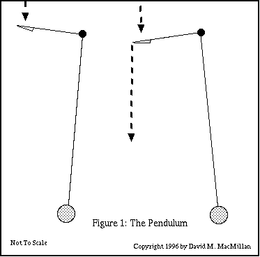
The pendulum in Gitton's Time-Flow Clocks is very simple. It is a pendulum whose length is appropriate to the clock. Frequently (always?) this pendulum is of glass and is filled with colored liquid.
At the pivot point of the pendulum, a rod extends out at right angles, in the plane of the swing of the pendulum. At the end of this rod is a small bowl. Water from a tank above the clock flows into this bowl at a rate which need not be constant. In all of the Time-Flow Clocks that I have seen illustrated, this bowl is enclosed within a glass globe. I presume, however, that this is merely to protect it, and that it operates at atmospheric pressure. (The pendulum and the rod to the bowl are always exposed, and there is no idication that there is a seal as the rod enters the globe which surrounds the bowl.) As the pendulum swings fully to the side opposite that on which the bowl is mounted, the bowl empties.
I have not actually witnessed the flow of water from the bowl in real time. However, it seems that the bottom of the bowl reaches the horizontal at or just before the pendulum swings fully to the "emptying" side (to the right in the diagram). If the bowl is of sufficient capacity, this would cause it to retain its contents until the pendulum swings fully to the emptying side.

This flow of water provides maintaining power to keep the pendulum going. Gitton also indicates that it can start the pendulum from a dead stop. He attributes this to fluctuations in the rate of flow, much like white noise triggering resonant behavior in an electronic circuit (HJ 18).
The impulsing of the pendulum in a Time-Flow Clock is not regular. The clock relies upon the fact that a pendulum is a resonator which, when impulsed randomly will tend to oscillate at a particular frequency (a frequency determined by its effective length). In traditional horology, it is recognized that a pendulum is not in fact a perfectly isochronous resonator, because its center of mass oscillates in a circular rather than a cycloidal path. It is for this reason that an attempt is made in precision (electro-)mechanical horology to impulse the pendulum by exactly the same force each time. The theory here is, I believe, that so long as the actual amplitude of the pendulum is the same on each oscillation, it does not matter that the pendulum is not isochronous over different amplitudes. These considerations do not, however, seem to be significant for Gitton's Time-Flow Clocks; they are public scientific sculpture, not observatory regulators.
This flow of water, which is a digital signal after the pendulum's bowl, also communicates the time signal to the rest of the clock; each emptying of the bowl is a "tick." This means that these Time-Flow Clocks are "free pendulum" clocks insofar as there is no possible way for the "going train" of the clock to influence the motion of the pendulum.
The "dividing siphons" which form the frequency divider in Gitton's clock form the equivalent of the "going train" in a mechanical clock: they take the unit time measurement (whose period is measured in seconds) and reduce its period to one appropriate for display (minutes).
The basic element of the frequency divider is what I will term here a "dividing siphon." However, before discussing the way in which Gitton uses a siphon to divide frequency, it is useful to review how a siphon works.
The easiest way to construct a siphon with which to experiment is to get a short length (say 10 cm) of clear plastic tubing of the sort sold (in the US) at home hardware stores (if you're lucky). Fill a glass with water. Over a sink, submerge the tube in the glass of water so that it, too, fills with water. Cover one end with your finger so that when you raise it above the level of the water it remains full. Raise one end of this tubing out of the water and put it over the side of the glass so that it is below the level of the surface of the water. You now have a siphon. Water will flow from the glass through the tube and into the sink until the level of water in the glass reaches the level of the output end of the tube (or the input end, of course, but we assume that you ensure that this does not happen).
This is the essential condition for siphoning: the level of the output must be lower than the surface of the water to be siphoned. Where the tube goes in-between doesn't matter. The surface tension of the fluid does matter (too big a tube or too "thin" a fluid won't work), but this will be ignored here.
Gitton's siphons were initially confusing to me because they consist only of tubing (though an examination of his work will show that the diameter of this tubing is not necessarily constant throughout the siphon). A "Gittonian" siphon is illustrated below.
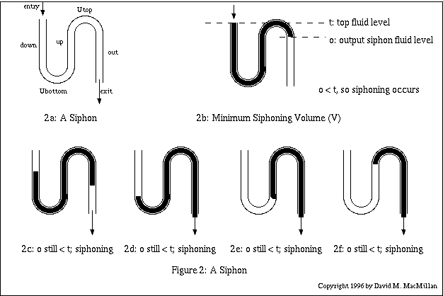
(For now, assume that the tubing in this siphon is of a constant cross-section.)
As this siphon is filled with water, there is a certain minimum volume, which will be designated V, which causes siphoning to occur. This volume is reached in Figure 2b, where the water just passes the upper (second) "U" and reaches a point where it is lower than the level of the water at the input.
Once this condition occurs, siphoning will continue until the siphon is drained. Consider the "worst case" situation where the input stops at the moment when siphoning occurs. As the sequence of figures from 2c through 2f shows, the siphoning continues -- with the output level continually lower than the level of fluid remaining in the siphon -- until the siphon is empty.
If input does not stop when siphoning occurs, siphoning still continues until the input ceases and the siphon is drained.
If the cross-sectional area of the output tube is less than or equal to that of the "down" and "up" tubes, then there will always be enough fluid in the output tube as siphoning occurs such that the output level is lower than the "surface" of the fluid in the "down" and "up" tubes. (The opposite is not true; in general, the output tube of the siphon needs to be of less volume than the vessel to be siphoned.)
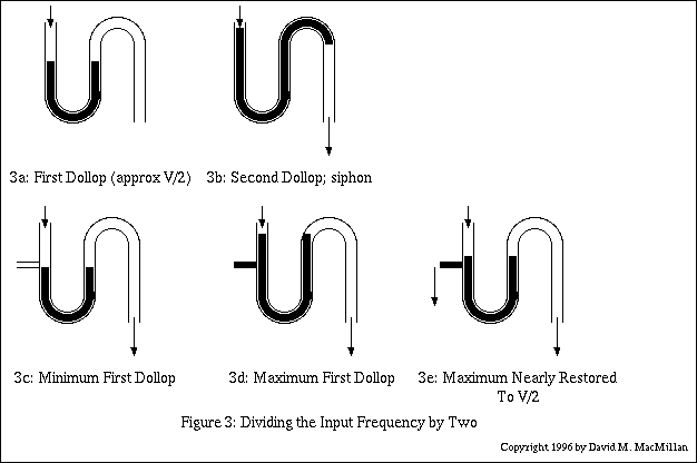
Figure 3 illustrates the way in which a siphon such as this may be used as a frequency divider. This example is modelled after the first siphon ("S1") of Gitton's Time-Flow Clock at La Villette, as described in his Horological Journal article.
The idea is that this siphon receives a sequence of "dollops" of liquid at intervals. In a siphon which divides by two, the first dollop of liquid should just sit in the siphon; the second should trigger it such that it empties (almost) completely. Thus, for i input dollops, you get i/2 output dollops (bigger dollops, of course, on output; this is taken into account when designing cascading dividers.) In general, in a siphon which divides by i, the first i - 1 dollops of liquid just sit in the siphon, and it triggers on the i-th.
In a siphon, once the conditions which induce siphoning occur, siphoning occurs relatively quickly. In the siphons of a Time-Flow Clock, "relatively quickly" means that the time it takes to empty the siphon is small in relation to the frequency of the incomping dollops of water. (That is, the siphon had better have fully emptied after dollop i before dollop i + 1 comes along.) Gitton has determined how to compensate for this if this siphoning time is not negligible (HJ 19), but this is not relevant to the discussion here).
Since this siphon is to divide by 2, the nominal volume of a dollop of water into this siphon will be just over V/2. After the first such dollop, the siphon is in the state shown by Figure 3a. Clearly, a second dollop of volume V/2 will cause the siphon to trigger and empty completely (Figure 3b).
If dollops of water could be relied upon to be the same volume each time, then this would end the matter. However, Gitton indicates that the incoming dollops can vary significantly in volume (and thus the outgoing dollops vary as well, a fact important when cascading dividing siphons). It is necessary to consider both the minimum and maximum acceptable volumes for a dollop.
For a single siphon (cascaded siphons introduce further complications) the minimum acceptable volume D for any dollop is V/i, where V is the triggering volume of the siphon and i is the number by which the siphon is to divide the input frequency. Thus, in the example here D = V/2. Intuitively, this must be so because the siphon must still function if, in the worst case, it is given just a sequence of minimum dollops. Thus, 2D must equal V, so D must be at least V/2.
The maximum acceptable volume D is that such that a siphon receiving i dollops of maximum D will be almost full (but not siphoning) on dollop i - 1. Gitton indicates that experiment has shown that for a Frequency/2 siphon this volume can be as high as (V/2) * 1.9.
When cascading siphons to further divide the input frequency, however, the subsequent siphons' design is very dependent upon the volume tolerance of the first siphon in the cascade (they aren't getting fluid from anywhere else, after all). The output of an F/2 siphon as described above could vary from V to just under 2V. Gitton improves upon this by adding a low (but sufficient) capacity drain at the level of fluid after a minimum dollop. If the first dollop is at the minimum value, nothing drains. If the first dollop exceeds this value, however, it drains to the minimum value before the second dollop. Thus, by the time the second dollop occurs, the siphon always contains a minimum first dollop of fluid. Since this minimum is V/2 and the maximum second dollop is almost V, the maximum output volume for this siphon is 3V/2. This is illustrated in Figure 3e.
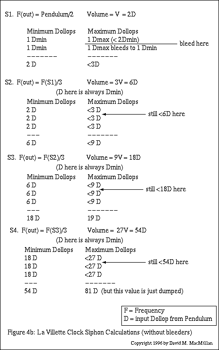
Consider first the concrete example of the Time-Flow Clock at La Villette. In this clock, the pendulum has a period of 2.222... seconds. There is a cascade of 4 dividing siphons, S1 through S4. S1 (volume = V) divides the pendulum frequency by 2 (output period 4.444 seconds), S2 (volume = 3 * S1 = 3V) divides S1 by 3 (output period 13.333 seconds), S3 (volume = 3 * S2 = 9V) divides S2 by 3 (output period 40 seconds), and S4 (volume = 3 * S3 = 9V) divides S3 by 3 (output period 120 seconds). Thus siphon S4 triggers every two minutes, providing a vacuum signal which fills another two-minute indicator in the minutes column, as described below.
The sizes of these siphons are not arbitrary. Each siphon which divides by n has a size such that it will always trigger when given n input dollops (whether they are minimum tolerance dollops or maximum tolerance dollops). These size of these dollops varies with each siphon; for the first siphon, they are as delivered from the bowl of the pendulum; for the subsequent siphons they are as delivered from the preceding siphon. The size of the output dollop from each siphon varies between certain minimums and maximums. As discussed above, for the first siphon's output, the minimum size is 2D and the maximum size is just under 3D.
Siphon S2 is designed to divide by 3. It must always trigger in the least case, when it receives three input dollops. I find it useful to work in terms of multiples of the minimum input dollop from the pendulum into S1, designated D. In the least case for S2, three minimal input dollops, each of size 2D, must trigger the siphon. However, the siphon must also be able to handle three input dollops of maximum size, 3D, and trigger only on the third. This it does. S2 has a volume of 6D. After two maximum input dollops of <3D, its volume must be just under 6D and it will trigger on the next dollop. Clearly, it's maximum output volume must therefore be 9D.
However, Gitton is not content with this. In his HJ article, he implies that there should be a small drain (what I call a "bleeder" drain), like the drain at level V/2 on siphon S1, on each of the siphons except the last. (What Gitton says, literally, is that for any pair of siphons, the first of the pair must have such a drain. Extrapolating from this, a cascade of siphons would have a drain on each siphon save the last.) This drain is located such that it drains a siphon intended to trigger after n input dollops to the level of n - 1 minimal input dollops. This means that the maximum output of each siphon is n - 1minimal input dollops plus one maximum input dollop. For instance, the maximum output of siphon S2 is 2D + 2D + 3D.
The siphons S2 and S3 operate in this manner. The siphon S4 has a maximum and minimum calculation that are similar, but it is not necessary to bleed this siphon as its output volume is simply dumped. (The output signal of S4 is a vacuum.)
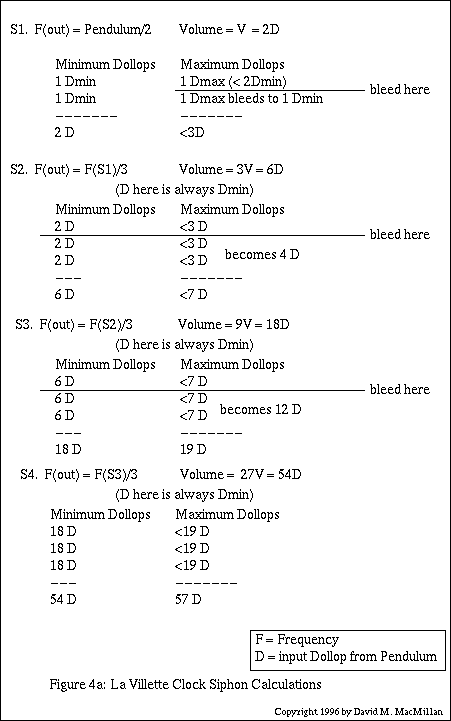
(I should note that neither on the diagram of the La Villette clock in Gitton's article nor on any photographs that I have seen of Gitton's clocks can I detect these drains on the second through the penultimate siphons. It seems to me that the La Villette clock, at least, would function without them even at theoretical maximum flows, but that the output volumes for each siphon would in the worst case be right at the limits of reliable operation.)
Figure 4b below reworks the calculations for the La Villette clock with drains on only the first siphon.
Finally, it should be noted that for any successive pair of siphons, there is a maximum possible division which can be reliably achieved for specific input tolerances. For instance, if the input dollops from S1 into S2 range from V to 1.5V, then S2 cannot be, say, 10 times the size of S1 (it cannot divide by 10). This is because S2 could potentially be filled and triggered by as few as 7 input dollops of the maximum volume (1.5V). The tighter the tolerances on input volumes, the greater the division that can be achieved in a single stage.
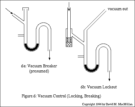
The first siphon in a cascade is open at its input to atmospheric pressure, as it connects directly to the globe surrounding the pendulum's bowl, which is at atmospheric pressure. The second through the penultimate siphons appear to each operate at atmospheric pressure through an opening which rises above the top of the input tube, as indicated in Figure 6a, below. It is not entirely clear to me why this is necessary, since it will never be the case that a siphon further down in the cascade triggers when all the siphons above it have not all just triggered. I presume that this vacuum breaking is necessary because given the delays of siphoning in the cascade a lower siphon might only trigger after S1 has received its first dollop of the next cycle (for example, after 2.222... seconds in the La Villette clock). The operation and rationale of this presumed vacuum breaker has not been verified.
The last siphon in a cascade, however, must not be allowed to operate at atmospheric pressure because on siphoning it generates a vacuum signal which is then transferred to the apparatus governing the minutes column. Neither must this vacuum be allowed to escape back along the dividing cascade. Gitton therefore incorporates an ingenious vacuum-lockout device at the entry to the last siphon of a cascade. As shown in Figure 6b below, the entry of tube to this siphon projects below the fluid level of a vial. (Note that in the diagram the fluid level inside the end of this tube is hatched with a different pattern than the fluid of the tube itself. This is just to show where the internal tube is; it's the same fluid.) All of the connections in this vacuum lock are airtight. Incoming fluid just spills over and enters the siphon. On siphoning, a vacuum is generated within the siphon. This vacuum is transferred out through the tube labelled "vacuum out." It is prevented from escaping via the entry tube by the fluid in the entry vial.
During the normal filling of this siphon, the siphon itself is maintained at atmospheric pressure via a bleeder valve, not shown, connected to the Minute Accumulator apparatus (and thus connected to the "vacuum out" tube).
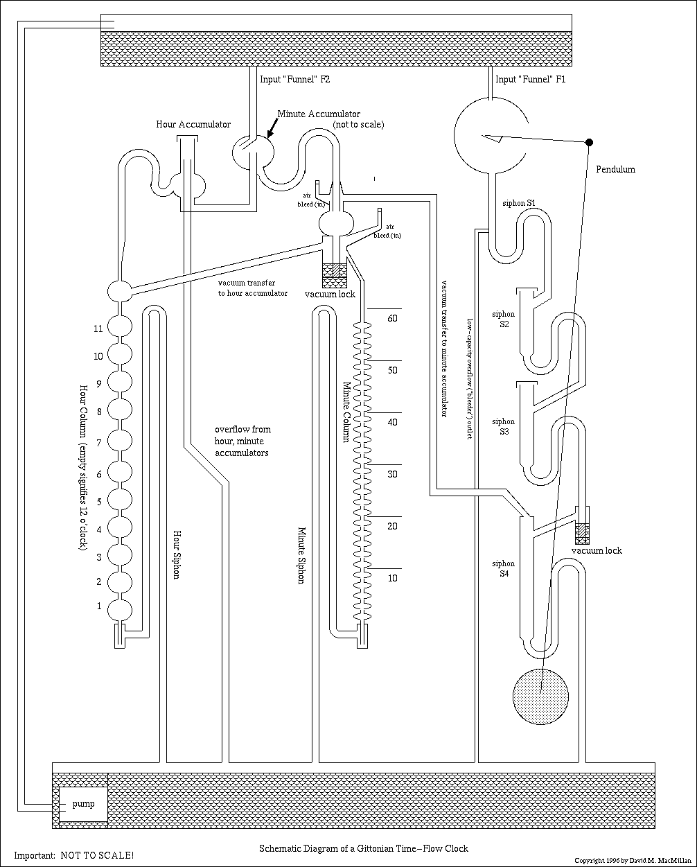
The Figure above represents a schematic view of a Gittonian Time-Flow clock. It does not represent any specific clock by Gitton. Gitton's clocks are much tighter in their layout, and much more aesthetically compelling. The diagram here is based loosely on the diagram of the La Villette clock as given in Gitton's Horological Journal article. Thus, it has four siphons in the dividing cascade. (It is possible to build a Gittonian Time Flow Clock with any appropriate number of dividing siphons.) In the diagram here, the layout has been changed to separate the functional units as much as possible. The diagram here is also not to scale. If you built a clock exactly like this it wouldn't work. In particular, the "Minute Accumulator" globe is far too big for the size of the minute column. I believe, though, that all of the siphoning levels are correctly indicated.
The operation of this clock may be "read" from right to left. Near the right is a pendulum, shown only symbolically. As discussed above, this pendulum has an attached bowl which collects "dollops" of water from the "Input Funnel F1" and the upper tank. It delivers these input dollops periodically to the first siphon, S1. The cascade of dividing siphons, S1 through S4, is shown on the right. (Again, this diagram is not to scale; the volumes of these siphons as depicted may not be accurate.)
When the fourth dividing siphon, S4, triggers, its contents are dumped to the lower reservoir. This creates, temporarily, a vacuum in the siphon. This vacuum is prevented from "escaping" (if one can think of a vacuum as a thing which flows) back through the cascade of dividing siphons by a vacuum lockout device. The only other place for this vacuum to go is up the "Vacuum Transfer" tube to the Minute Accumulator.
While all of the input division is happening, a second Input Funnel, F2, is delivering liquid into the globe of the Minute Accumulator. This Accumulator should be designed such that it is filled and has partially overflowed during one complete "input cascade" calculation. (In the La Villette clock, this is a period of two minutes.) The overflow from the Minute Accumulator will be discussed below in the section on the Hour Counter.
In Gitton's La Villette clock, the Minute Accumulator can slide up and down its central drain to vary its volume. In this way, the clock may be adjusted to deliver the correct volume to the Minutes Column.
Each time a vacuum is created by the siphoning of S4, then, there is a full Minute Accumulator. The vacuum in S4 is transferred to the output tube of the Minute Accumulator (the Minute Accumulator is, of course, itself a siphon). The decreased pressure here triggers this siphon by pulling liquid down the output tube. This empties the contents of the Minute Accumulator into the Minute Column. The volume so emptied is designed to fill up another marker in this column (not forgetting that it must also fill the Minute Siphon to the same level). In the La Villette clock, each marker in the Minutes Column indicates two minutes.
An input air bleed restores the pressure on the output end of the Minute Accumulator to atmospheric.
The top marker in the Minutes Column indicates 58 minutes. When the next volume from the Minute Accumulator is emptied into the Minute Column, the volume of the column exceeds the triggering capacity of the entire column (which is, naturally, a siphon). This causes the entire Minutes Column to siphon and empty. The time period from zero minutes to (just under) two minutes is indicated by an empty column.
When the Minutes Column siphons, its contents are dumped to the lower tank. This creates, temporarily, a vacuum in the Minutes Column. This vacuum is transferred to the Hour Accumulator, just as the vacuum from the siphon S4 was transferred to the Minutes Accumulator.
During the course of each hour, the Minute Accumulator fills to just over full 30 times. The excess from this filling leaves the Minute Accumulator through a drain in its middle and is transferred to the Hour Accumulator. The Hour Accumulator, naturally, accumulates enough liquid to fill the Hour Column by one hour-marker. Any excess liquid drains out of the Hour Accumulator's central drain into the bottom tank. Like the Minute Accumulator, the Hour Accumulator may be slid up and down this drain to adjust its volume.
When the vacuum from the Minutes Column is transferred to the top of the Hour Column, it triggers the Hour Accumulator siphon and fills the Hour Column and the Hour Siphon by another unit. On the clock as drawn, 11 o'clock is indicated by eleven full globes in the Hour Column. 12 o'clock is indicated by an empty Hour Column. Gitton indicates that he has also built clocks which indicate 1 through 12 by full globes. To do this, it is simply necessary to ensure that the 1 o'clock globe never empties.
The hydraulic logical gate developed by Gitton consists of two input pipes, A and B, representing the logical input signals. The presence of fluid flow indicates "on" or "1" while its absence indicates "off" or "0." These two input pipes meet in a chamber equipped with one exit siphon (C) and at a slightly higher level one exit drain (D). This general arrangement may be seen on the left in the figure below.
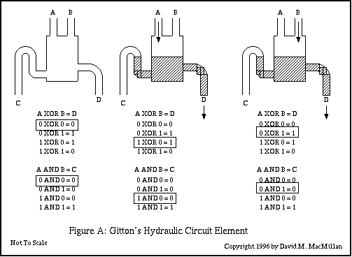
This logic circuit directly implements two operations: logical AND and logical EXCLUSIVE-OR (XOR).
Of these, XOR is the easiest operation to see. If input A is the only one flowing, then the chamber fills to some point such that the output drain D is flowing and the output siphon C is not triggered. (Clearly, the flow levels must be chosen appropriately, so that the flow into A is not so great as to trigger the output siphon C.) The situation is the same if B is the only input flowing. However, if both A and B are flowing, the level in the chamber exceeds that necessary to trigger the output siphon C and this siphon empties the chamber. Thus, output D flows if A XOR B is flowing (but not if both are flowing, which is the "eXclusive" in XOR).
The AND operation follows naturally from this. If A and B are flowing, then exit siphon C flows; in all other situations, exit siphon C does not flow.
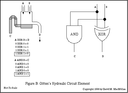
The conventional circuit-symbol representation for this hydraulic circuit element is given in Figure B, above.
A logical NOT gate can be constructed by noting that if one input of an XOR gate is held high, the gate functions as a NOT gate. For instance, ensure that input B is always flowing. If input A is not flowing, then output drain D is flowing. If input A is flowing, then the output siphon C is triggered and output drain D is not flowing.
At the Cité des Sciences et de l'Industrie, La Villette (Paris, France), Gitton has built a 4-bit binary adder using liquid logic circuits such as these. He terms such a machine "l'eaurdinateur" (eau = water; ordinateur = computer) - a beautiful phrase.
What I posess by the courtesy of M. Gitton is a typewritten English-language article as titled above, together with a color photocopy of the cover of the magazine Hypothèse. I assume that this is a translation done by Gitton's studio of an article which appeared in this magazine. I have not seen the original article in French.
This article discusses in some technical detail the siphon-based logic gates invented by Gitton, as well as their use in a 4-bit binary adder installed at the Center for Science and Industry at La Villette (Paris).
This article by Gitton himself covers in technical detail the operation of a representative water clock. The Time-Flow Clock illustrated on the cover of this issue is not identified within, but it is the 2.3 meter high clock installed at the Cité des Sciences, La Villette, Paris.
Horological Journal is the official publication of the British Horological Institute (BHI) and the British Clock and Watch Manufacturers' Association. Further information on it is available from the The British Horological Institute
Chéné, Bruno. Photo by Alain Le Bot. "Son horloge a séduit les Japonais." Le Journal du Dimanche. No. 2422 (16 Mai, 1993): [page 1?]
This article illustrates Gitton's chaotic movement fountain entitled at Butterfly Effect at Longué-Jumelles, France.
De Cherisey, Thérèsa. Photos by Éric Morin. "Gitton le démiurge ou le rêve de l'immortalité." Décoration Internationale. (November/December, 1988): 106.
Translated by Gitton's studio as "Bernard Gitton or The Dream of Immortality."
Mariez, Alain. Photos by Patrick Levaud and Patrick Robert. "Portrait: Bernard Gitton, le magicien d'eau." L'Angou. (June, 1995): 9-15. ISSN: 0992-0227.
There is a reference in Gitton's Horological Journal article which reads: "Pendulum clock working by means of water - M PERRAULT. Rec. des Machines Tome I f p 39."
Phyllis and Mike Chaney have helped me track this reference further. Baillie's Watchmakers and Clockmakers of the World lists a bibliographic reference for:
Perrault, Charles. ----- [place of work unknown].
b. 1613, d. 1688.
Pendulum clock driven by water. Conservatoire des Arts et Metiers, Paris. Desc. in Gallon, Machines et Inventions Vol. 1.
The Chaneys further traced Gallon to:
Gallon. Machines et Inventions approuvees par l'Acadamie Royale des Sciences depuis son etablissement jusqu'a present; avec leur Description. ["Machines and Invenstions approved by the Academie Royale des Sciences, from its initiation to date; with their description."] Gabriel Martin, J.B. Coignard fils, H.L. Guerin. Parix MDCCXXXV. Six volumes 9 1/2 x 8.
Perrault is referenced in Tome I (Depuis 1666 jusqu'en 1701), as noted by Baillie below.
Baillie, on page 80, discusses Perrault. He lists a 1669 letter from Claude Perrault to Christiaan Huygens on the subject of a hydraulic pendulum clock. The location of the original is given as: MS. Leiden and copy in MS. Français No. 21259, Bibl. Nat. Reproduced in Oeuvres Complètes de Christiaan Huygens, Vol. VI. The Hague, 1895. (No reply by Huygens known.)
Baillie indicates that Perrault (1613 - 1688) was a doctor who turned to architecture. (He constructed the facade of the Louvre.) Baillie says that Perrault presented a memoir to the Académie concerning his clock at some time before 1669. Ballie indicates that this memoir, together with a plate, was reproduced in Gallon (see above), Volume I, Paris, 1735: pages 39, 40. A second memoir and plate, concerning a striking mechanism, appears on page 41-43 of Gallon. Baillie reproduces the first of these plates, and indicates that this design was workable, although additions to this design in the letter to Huygens are, in Baillie's view, not workable.
There is a reference in Gitton's Horological Journal article which reads: "Flow by Zanucci - see Bouasse 'pendule spiral' Tome 1 p 291."
Phyllis and Mike Chaney have helped me track this reference further. They have discovered two works by Henri Bouasse listed in the British Library's French Catalog:
Bouasse, Henri. Bibliotheque scientific de l'ingenieur et du physician. 46 tom. [volumes].
Bouasse, Henri. Pendule, spiral, diapason. 2 tom. [volumes]. 1920.
Mike Chaney further concludes from an analysis of the bibliographic material on Bouasse that Bouasse was not a horologist but rather a learned scientific writer.
Mike Chaney, an engineer and modelmaker, has a WWW page at:
http://wkweb4.cableinet.co.uk/mikechaney
This is just a personal note (DMM).
I think it would be neat to combine the liquid circuitry of a Gittonian Time-Flow Clock with the liquid impulsing of the Earl of Meath's free pendulum clock. There are two aspects of this: impulsing the pendulum with great regularity and getting a dollop of water out at each time unit.
The first of these matters is easy. A Meath-style water-impulsed pendulum would work "out of the box" in conjunction with a Gittonian Time-Flow Clock. The upper tank and funnel of Gitton's clocks and of Meath's clock are functionally identical. The second matter, that of getting a constant dollop of liquid, could be solved in several ways. One of the most obvious would be to take the finite-length "column" of water which impulses the pendulum in Meath's clock and use it as the input dollop - instead of diverting it to the drain, divert it to the input siphon of Gittonian liquid clockwork. The water which triggers the "escape pallet" in Meath's clock would, in this scheme, just be drained away without doing anything. Such a clock would run out of phase with a "pure Meath" clock, but this shouldn't be an issue.
With the exception of any material noted as being in the public domain, the text, images, and encoding of this document are copyright © 1996-1998 and 2000 by David M. MacMillan.
This document is licensed for private, noncommercial, nonprofit viewing by individuals on the World Wide Web. Any other use or copying, including but not limited to republication in printed or electronic media, modification or the creation of derivative works, and any use for profit, is prohibited.
This writing is distributed in the hope that it will be useful, but "as-is," without any warranty of any kind, expressed or implied; without even the implied warranty of merchantability or fitness for a particular purpose.
In no event will the author(s) or editor(s) of this document be liable to you or to any other party for damages, including any general, special, incidental or consequential damages arising out of your use of or inability to use this document or the information contained in it, even if you have been advised of the possibility of such damages.
In no event will the author(s) or editor(s) of this document be liable to you or to any other party for any injury, death, disfigurement, or other personal damage arising out of your use of or inability to use this document or the information contained in it, even if you have been advised of the possibility of such injury, death, disfigurement, or other personal damage.
All trademarks or registered trademarks used in this document are the properties of their respective owners and (with the possible exception of any marks owned by the author(s) or editor(s) of this document) are used here for purposes of identification only. A trademark catalog page lists the marks known to be used on these web pages. Please e-mail web@lemur.com if you believe that the recognition of a trademark has been overlooked.
Version
1.18, 2000/09/18.
Feedback to web@lemur.com
http://www.database.com/~lemur/dm-gitton.html
Go to the: