Delightful Machines
By David M. MacMillan
1. General
2. Biographical Information on the Earl of Meath
3. The 1903 Clock
4. The 1906 Clock - Overview
5. The 1906 Water-Impulsed Pendulum
6. The 1906 Going Train and Motion Work
7. The 1909 Striking Train
8. Other Clocks by the Earl of Meath
9. Bibliography
Legal Matters
(8 drawings, approximately 31.2 kilobytes total; approximately 34.1 kilobytes of text)
If you are seriously interested in the Earl of Meath's water clock, you should obtain the published firsthand accounts of it:
Additionally, Aked's 1986 NAWCC Bulletin article contains photographs of Killruddery House not found in the other two.
In the first decade of the Twentieth Century, the 13th Earl of Meath (Ireland) created a clock whose pendulum achieved the desirable property of being entirely free of the escapement. This property is theoretically desirable because a pendulum whose motion is not influenced by an escapement should be able to perform its function, regular oscillation, more accurately than one which is coupled to an escapement. Meath built his original clock in 1903 and modified the escapement and going train to the current version in 1906. A striking train was either added or modified to its current version (the sources are unclear) in 1909. Both the going and striking trains are powered by water.
Charles K. Aked (1986) cites Lord Kelvin (Sir William Thompson) as the builder of the first free pendulum in 1865. Aked notes that one free pendulum clock by Kelvin is preserved in Kelvin's house in Professor's Row, Glasgow University, and that a later design exists in the Science Museum, London. H. Alan Lloyd (1958) was apparently unaware of Lord Kelvin's free pendulum clocks. Both Aked (1986) and Lloyd (1958) note an 1898 free pendulum clock by R. J. Rudd. Aked says that this example is in the Science Museum, London, but that it has not been possible to keep it running "for any length of time." The free pendulum clock was taken to a high state of development in following years by William Hamilton Shortt (1921 and after) and others, and for a time free pendulum clocks were the most accurate clocks available.
Although these other free pendulum clocks did not use the "water escapement" devised by the Earl of Meath, it is nevertheless to this tradition of precision free pendulum timekeeping that I feel his clock belongs. Meath's clock was created from surplus parts and outright junk, and is exquisitely engineered to be accurate despite the humble origin of some of its components. This clock is an experiment in technology, not a public sculpture. Water-impulsed pendulum clocks have also been created by the French physicist and artist Bernard Gitton. However, although Gitton's clocks are quite accurate when properly maintained, I feel that Gitton's clocks belong not to the tradition of precision free pendulum timekeeping but rather to the tradition of public scientific sculpture.
Moreover, while both the Earl of Meath and Gitton employ water and pendulums, the principles by which their clocks operate are entirely different. Meath devised an innovative water-based escapement, but for the going train itself used conventional wheelwork. Gitton's escapement is less sophisticated, but he has replaced the wheelwork of a going train with a fascinating hydraulic calculating system.
Meath's clock resides in Killruddery House, Bray, County Wicklow, Republic of Ireland. (Lloyd calls this "Kilruddery Castle".) Killruddery, though in County Wicklow rather than County Meath, is the traditional seat of the Earls of Meath. It is located about 12 miles southeast of Dublin.
Question: Does anyone know how I might obtain illustrations for reproduction here of the Earl of Meath's clock (from his descendents? from others?)
Question: What else did the Earl of Meath do? Surely such an ingenious clock cannot be his only work!
The following information is derived primarily from Aked (1986). Information on the full names and dates of Meath's parents, the 12th Earl and Countess, have been derived from the US Library of Congress subject headings as present in the University of Michigan's online library catalog.
The biographical data I have on the 13th Earl of Meath is sketchy. His father was Reginald Brabazon, 12th Earl of Meath, K.P., who lived from 1841 to 1929 and who published several works. His mother was Mary Jane Maitland Brabazon, Countess of Meath, d. 1918. Her diary was edited and published by her husband, and she contributed to her husband's published writings. The 13th Earl of Meath assumed that title on the death of his father in 1929, together with the Barony of Chaworth, Eaton Hall, County Hereford.
Thanks to Louis Epstein for the following information on the names of the 13th and 14th Earls:
The 13th Earl of Meath's full name was Reginald le Normand Brabazon. His widow died in 1962. His son, the 14th Earl, was born on Nov. 3, 1910, and was named Anthony Windham Normand Brabazon. There is a rumor that the 14th Earl passed away recently.
I don't know the 13th Earl's birthdate. He died in March, 1949, at Killruddery (Aked says "two months after" Lloyd's first description of his clock in the January, 1949 Horological Journal). Aked says that he was educated at Wellington College. He was commissioned in the Grenadier Guards in 1889. He served in the Boer War and was decorated with the Queen's Medal, three clasps, and the King's Medal, two clasps. (The Boer War extended from 1899 to 1902; the Earl's dates of service are not known to me.) It was during this period that he conceived of the water clock. He served again in World War I, and was gassed in 1918. At the conclusion of his service, he had attained the rank of Brigadier General. Aked notes that his other vocation was gardening, and indeed the gardens at Killruddery now figure more highly in tourist books than the house itself.
The tourist guide of Ireland that I happen to have at hand is: Eyewitness Travel Guides: Ireland (London: Dorling Kindersley, 1995). The following information comes from its short entry on Killruddery House. It says that Killruddery is south of the seaside resort town of Bray, near Little Sugar Loaf Mountain. It was built in 1651 and has always been the family seat of the Earls of Meath. It was remodelled in the Nineteenth century in an "Elizabethan Revival" style. The original gardens were laid out in 1680 by one Bonet, a French gardener. They contain a sylvan theater, unique in Ireland, as well as two Long Ponds of 165 meters length. There is no mention of the contributions of the 13th Earl. This guide cites these gardens as "the finest French Classical gardens" in Ireland. The phone number for Killruddery House is 01 2863405. It is said to be open May, June, and September daily, in the afternoon. Admission is charged and handicapped access is limited.
Both the 1903 water clock and its 1906 successor were built in the gatehouse to the outbuildings at Killruddery. This building and its location relative to the other buildings of Killruddery are illustrated in Aked (1986).
Prior to the installation of the 1903 clock, there existed a clock in this gatehouse. Aked (1986) (128) indicates that that the current (1909) striking train was adapted from this clock. It was made by Lund and Blockley, Pall Mall, London.
Aked (1986) indicates that the 1903 clock was impulsed on both sides of the pendulum, whereas the 1906 clock is impulsed on one side only. He says of the 1903 clock that:
Under the pendulum bob were equilateral-shaped pallets having concave sides on which the controlled water column impinged... (Aked 1986, 128)
Aked indicates that this design was thought by Meath to be superior in principle, but troubled by practical considerations such as splashing.
Meath's 1906 clock is distributed throughout the gatehouse tower it occupies; it is not possible from the published illustrations to fully reconstruct the appearance of the clock. This is, if anything, a significant feature of the clock, indicative of the degree to which Meath successfully decoupled the various motions of the ensemble.
The clock is regulated by a pendulum. Lloyd (1958) gives the period of the pendulum as 1.25 seconds and the weight of the bob as 1 cwt. Aked confirms this period and gives the weight of the bob as 112 pounds. He further indicates that this pendulum is made from "the front of" an old artillery shell, that it is suspended by a 1 inch diameter steel rod, that it is compensated by a zinc tube placed below the bob, and that it may be further adjusted by a small weight about one third of the way up from the bottom of the pendulum rod which. The pendulum's swing is readable in degrees from a scale placed below it; this scale reads up to 1.5 degrees in either direction. The pendulum's swing is enclosed in a wooden box.
The pendulum, however, is completely decoupled from the going train. Indeed, the plane of its swing is at an angle to the axes of the going train.
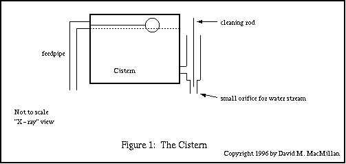
Tracing the flow of water through this clock might be the best way to get a general idea of its operation. Water is first collected in a cistern near the ceiling. Aked's 1986 article indicates that this cistern was indeed manufactured for use in a bathroom. The level of water in this cistern is controlled by a simple float. Water escapes from this cistern through an arrangement of pipes which allows the use of a cleaning rod to keep the release orifice free from deposits.

The stream of water falling from this cistern both impulses the pendulum and transmits the pendulum's time signal to the going train. It is collected below the escapement and channelled into a waterwheel constructed of a cycle wheel (I can't tell from the published accounts whether this is a bicycle or a motorcycle wheel). Aked indicates that this waterwheel gives about 20 ft/pounds of force, which is transmitted to the train by a sprokets and cycle chain.
After it is done powering the train, the water is by no means done, for it still has to power the striking mechanism. As it leaves the waterwheel, it is collected in another tank. Through a mechanism described below, this tank's contents are emptied every hour. It then passes through an intermediate tank and into a suspended tank where the water both actuates and provides the power for the striking mechanism. At this point, the water is released to a waste pipe, although Aked indicates that the Earl once considered a fountain.
Let's consider Meath's pendulum design in stages.
A pendulum is an oscillator which should provide a stable time signal; the function of the rest of a clock, really, is to interpret that time signal. (One can keep time just by counting oscillations. One cannot keep time with any amount of wheelwork without a stable oscillator.) An oscillator, then, must produce the following signal on its output:

How the oscillator produces this signal is its own business.
In Meath's clock, this signal is indicated by the presence or absence of a vertical flow of water. The state of this signal is communicated to the mechanism of the clock by means of a pallet which is either pressed down by the water or (by some mechanism not shown) sprung up:
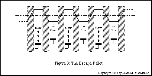
Note that the amount and force of the water hitting the escape pallet is not critical. It needs to be enough to depress the pallet fully, and not so much that the pallet is damaged. Within these limits, however, the amount of water may vary without affecting the accuracy of the transmission of the signal. It is the presence or absence of water that is the signal. Meath's clock is thus, at this point in its operation, digital.
The shaded areas in Figure 2 represent the transitional period during which the oscillator changes state and during which the escape pallet stabilizes in the new state (the second of these two periods should be contained within the first). It is assumed that the escapement is designed to correctly accomodate these transitions.
Meath's clock is a "free pendulum" (or, given our discussion so far, "free oscillator") clock because as is apparent from the figures there is a communication of energy or information from the oscillator to the escapement, but no corresponding communication from the escapement to the oscillator.
Working "up" from the escape pallet, we come now to the internals of the oscillator.
The oscillator must, of course, turn the stream of water on and off. It does this by interrupting the stream of water with a pallet which we shall call the interrupting pallet. (Lloyd calls this the "deflector pallet.") Imagine that our oscillator is an extremely patient and accurate genii. Such a creature might, simply, shove an inclined plane into the stream of water when the stream needed interruption.
Graphically, a single period of oscillation looks like this:
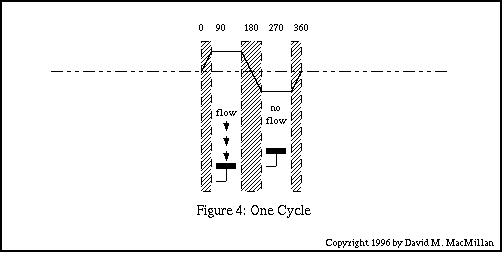
It is possible to assign degree numbers to the various positions along this cycle since this is a harmonic motion which can in theory be resolved into a rotary motion.
The minimal action of the interrupting pallet during a single cycle is this:
Imagine that our genii is in fact a pendulum maintained in regular oscillating motion at (more or less) a certain amplitude. (The mechanism which maintains the pendulum's motion will be described later.)
(Note: The descriptions here will assume that the pendulum is being viewed face-on to the plane of its swing. A "right" and "left" are meaningful within such a viewing context.)
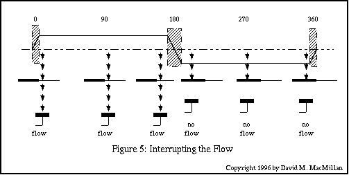
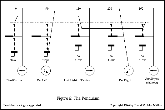
Consider the pendulum at dead center, in the process of swinging to the left. At this point (arbitrarily 0 degrees in the figure below) the interrupting pallet is clear of the stream of water. If we assume that the previous state of the stream of water was interrupted, and that the escape pallet was previously down, then there will be a short period during which the water flows to reach the escape pallet and during which the escape pallet is pressed down. During the whole of the swing left and back to center, the interrupting pallet is clear of the stream of water and the escape pallet thus remains depressed.
As the pendulum swings right of center, the interrupting pallet cuts the stream of water and diverts it away from the escape pallet. At this point, it will take a short time for the water beneath the interrupting pallet to finish falling and for the escape pallet to rise. During the whole of the swing to the right and back to center, the interrupting pallet diverts the stream of water away from the escape pallet, and the escape pallet consequently remains up.
Note also that both the full-flow and the no-flow states continue for just a bit longer than our previous graphs have indicated. As the mechanism of the clock should be designed to ignore the state of the escape pallet during these periods, this is of no consequence.
The interrupting pallet (called by Lloyd the "deflecting pallet") needs to be long enough to divert the stream of water through the entire right-hand portion of the pendulum swing. It is thus a bit longer than the amplitude of the pendulum's swing at the point where it is mounted.
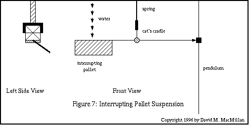
The actual construction of the interrupting (deflecting) pallet and its mounting is slightly more complex than indicated above. I presume that the reason for this is to isolate the pendulum as much as possible from the effects of the interrupting pallet (e.g., torque).
The interrupting pallet is attached to a horizontal rod. This rod is suspended from a thin vertical spring. Lloyd doesn't indicate the length of this spring, but I will assume that its suspension point is at the same level as that of the pendulum. I will futher assume that the suspension point is such that the vertical spring and the pendulum are mounted such that they are parallel (when at rest; see below). If the iterrupting pallet is viewed at the left end of this rod, then the right end touches, but is not in fact connected to the pendulum. Lloyd indicates that it is held in contact with the pendulum during the rightward swing (when it otherwise would tend to separate from the pendulum) by a slight pressure from the vertical spring. As described so far, the motion of the interrupting pallet's horizontal bar forms the bottom link of a four-bar linkage in the form of a parallelogram. It thus remains horizontal. Note, however, that I have made two significant assumptions about the length and suspension point of the vertical spring.
The vertical spring is not, however, directly attached to the interrupting pallet's horizontal bar. Instead, it is attached via what Lloyd calls a "cat's cradle" of silk thread. This is best described visually in the figure below.
If the pendulum could continue in regular oscillatory motion indefinitely, then the mechanism would be complete at this point. The swing of the pendulum will decay, however, under the inescapable influence of friction. Some method is necessary, therefore, to give the pendulum a regular impulse to keep it going.
It is important that this impulse be uniform and that it be delivered at the same time each swing. (Is this true? Meath assumed it was.) Meath achieves this goal by isolating a fixed-length column of water (assumed to be of fixed diameter) at each rightward swing and using its constant force to impulse the pendulum.
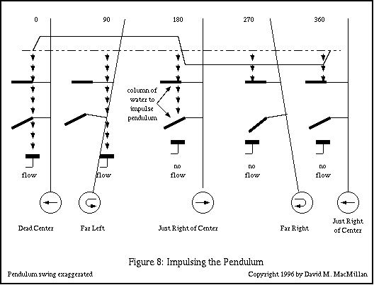
As seen in the figure below, an impulse pallet is rigidly attached to the pendulum. (Lloyd calls this the "impelling pallet.") It is oriented directly below the interrupting pallet. Both it and the interrupting pallet are in the plane of the swing of the pendulum. The impulse pallet is in the form of a trough held at an angle. When water flows into it, it carries this water safely away from the escape pallet and at the same time delivers a part of the energy of that water to the pendulum.
The right-hand edges of the interrupting pallet and the impulse pallet are so arranged that when the pendulum is at dead center the interrupting pallet's right edge is directly above the impulse pallet's right edge. Both pallets are just to the left of the stream of water.
As the pendulum moves right through dead center, the interrupting pallet cuts the stream of water. At this instant in time there is a column of water falling through the air between the interrupting pallet and the impulse pallet. (In Meath's clock this column is nine inches high.) At the same time that the interrupting pallet isolates this column of water from the stream, the impulse pallet moves to catch it. Thus, on each rightward swing of the pendulum, a nine-inch column of water provides the maintaining impulse for the pendulum.
The mechanism described controls the height of the column of water impulsing the pendulum, but it does not control its diameter. This is controlled by the tank supplying the water. The level of water in this tank is maintained by a simple ball cock, and the outlet for this tank is of fixed diameter. Presumably, these two are adequate to provide a sufficiently constant flow.
Note also that the impulse pallet is "covered" by the interrupting pallet during the full swing to the right and back. Thus, the only water which can ever strike the impulse pallet is that column of water already below the interrupting pallet (and yet still above the impulse pallet) at the instant the interrupting pallet cuts the stream of water when moving to the right.
The going train and motion work of this clock are implemented with wheelwork. I can't make out much detail of them from Lloyd's account or photograph. The display appears to be conventional. Lloyd indicates that the trains are water powered.
Aked (1986) (128) indicates that the going train was made to Meath's specifications by the firm of Chancellor, Grafton Street, Dublin, and that it is 12 inches long by 6 inches wide.
Lloyd (1958) (138) indicates that the striking train was added in 1909. Aked (1986) (128) indicates that the striking train existed prior to this, but that it was converted from the use of a bell to the use of the existing tubular gong in 1909. He also notes that this tubular gong was "one of a set" (128) used at the 1906 St. Louis (USA) Exhibition. Aked does not indicate what its function was at the exhibition, nor can he determine (after having reviewed Meath's papers) how this gong came to Killruddery.
The striking train contains a number of mechanical components, but is actuated and powered by water. It also contains a siphon to achieve the rapid movement of a large quanity of water on the receipt of a time signal. This brings to mind the siphons of the water clocks of Bernard Gitton.
Clock in the Hall at Killruddery. Two seconds pendulum (approx 13 feet). Illustrated and very briefly described in Aked's 1986 article (page 123 and figure 2).
Collaborations with G. B. Bowell, noted in Aked's 1986 article (131). One of these clocks is said by Aked to be in the Science Museum, London.
"Q" clock. Aked, in his 1986 article (131), notes a letter by Professor Torrens to the Editor of Horological Journal in reference to this clock. It remained unfinished at the Earl's death in 1949. It's apparent design goal was to eliminate amplitude error.
Note:
Back issues of the NAWCC Bulletin may be obtained from the
National Association of Watch and Clock Collectors
514 Poplar Street
Columbia, PA 17512-2130
USA
(717) 684-8261
http://www.nawcc.org/nawcc/
Back issues of The Clockmaker may be obtained from the
TEE Publications
100544.1675@compuserve.com
Aked, Charles K. "An Hydraulic Time Machine". NAWCC Bulletin. Vol. 82, No. 2; Whole No. 241. (April 1986): 122-131.
At the time this article was written, Aked had not visited Meath's clock. There are some errors in this initial account. In particular, his description of the striking train seems to be incorrect. Alan Heldman indicates that Aked's 1988 article in the NAWCC Bulletin article, written after a visit, corrects errors in this initial account. Aked's 1990 article in The Clockmaker is also free of these misconceptions. This article contains photographs of Killruddery House, including an arial photograph. It also contains a photograph of the Earl's 2 seconds pendulum clock in the Hall at Killruddery and references to Meath's later clocks, including his last, "Q," clock.
Aked seems to have used many of the same photographs as Lloyd (1958). Aked's Figure 3 (the gatehouse) is the same as Plate 163a in Lloyd. Similarly, Aked's Figure 4 (the general layout of the clock, except the striking train) is the same as Lloyd's Plate 163b; Figure 9 (the going train) is Plate 164a; Figure 7 (the exterior of the water impulsing mechanism) is Plate 164b; Figure 10 (the striking train) seems to be a portion of Lloyd's Plate 165. However, some of the photographs in Aked's article seem to have been retouched for clarity (lines seem drawn in in Figure 3, while Figure 4 seems to have three wooden beams omitted).
Aked, Charles K. "The Kilruddery Clock: An Hydraulic Time Machine - Some Details of the Striking System." NAWCC Bulletin Vol. 30, No. 6; Whole No. 257. (December, 1988): 475-483.
This article describes Aked's first visit to the clock. It presents some fine photographs of both the time and the strike systems, and outlines the operation of the striking mechanism in detail. This article and Aked's 1990 article article in The Clockmaker (which duplicates some of this material) are, to the best of my knowledge, the only published firsthand technical accounts of the clock.
Aked, Charles K. "The Earl of Meath's Water Driven Clock." The Clockmaker. Vol. 1, No. 4 (Oct/Nov 1990) and Vol 1, No. 5 (Dec 1990/Jan 1991). Tee Publications (UK). Part 1: 103-105; Part 2: 127-128.
Lloyd, H. Alan. "A Modern Clepsydra." Horological Journal. January, 1949.
[I have not yet examined this article.]
Lloyd, H. Alan Some Outstanding Clocks over Seven Hundred Years. London: Leonard Hill [Books] Limited, 1958: 138-140, Plates 163 (a, b), 164 (a, b), 165.
Torrens, Professor [first name?]. [letter to the Editor] Horological Journal. [near 1949].
This reference is noted in Aked's 1986 article. The letter concerned not the Earl's water clock but his unfinished "Q" clock. I have not yet had the opportunity to read this letter.
Thanks to Mike Chaney for bringing Aked's The Clockmaker articles to my attention, and to Alan Heldman for first bringing Meath's clock to my attention and for the reference to Aked's 1988 NAWCC Bulletin article.
The following horologists are known to have visited the Earl of Meath's water clock. Bibliographic searching of their writing might turn up more information.
Charles K. Aked (June 1987, with Dr. A. A. Mills)
H. Alan Lloyd (1949)
Dr. A. A. Mills (of Leicester University, in 1987, with Charles K. Aked)
Alexander Steuart (of Edinburgh, in 1949, with Professor Torrens)
Professor Torrens (1949, with Alexander Steuart)
Additionally, it is probably safe to assume that G. B. Bowell, whom Aked notes in his 1986 article (131) as having collaborated with Meath, knew of and probably visited this clock.
I have not yet had the opportunity to read any of these.
Meath, Mary Jane Maitland Brabazon, Countess of, d. 1918. The Diaries of Mary, Countess of Meath. Edited by her Husband. v. illus., ports. London: Hutchinson, < 1928-.
Meath, Reginald Brabazon, 12th Earl of, 1841-1929. Memories of the Nineteenth Century, by Reginald, 12th Earl of Meath, K.P. viii, 354 p. front., plates, ports. 23cm. New York: E.P. Dutton and company, 1923.
Meath [presumably the 12th Earl, as the 13th Earl did not ascend to the title until 1929]. "London as the Heart of Empire." in Sir Aston Webb, Ed. London of the Future, by the London Society under the Editorship of Sir Aston Webb. 286 p., 1 L. front., plates, plans. 26 cm. London: T.F. Unwin, Ltd., 1921.
Meath, Reginald Brabazon, 12th Earl of, 1841-1929.
Prosperity or Pauperism?
Physical, Industrial, and Technical Training.
3 p.l.,
Meath, Reginald Brabazon, 12th Earl of, 1841-1929. Thoughts on Imperial and Social Subjects, by the Right Hon. the Earl and the Countess of Meath. x, 290 p. 19 1/2 cm. London: T. Cardner, Darton and Co., Ltd., 1906. [Four concluding chapters by Mary Jane Maitland Brabazon, Countess of Meath, d. 1918.]
There is a reference in Bernard Gitton's Horological Journal article Which reads: "Pendulum clock working by means of water - M PERRAULT. Rec. des Machines Tome I f p 39."
This reference is traced more fully in the page on Bernard Gitton.
There is a reference in Bernard Gitton's Horological Journal article which reads: "Flow by Zanucci - see Bouasse 'pendule spiral' Tome 1 p 291."
This reference is traced more fully in the page on Bernard Gitton.
I have received great assistance in tracing these references from Phyllis and Mike Chaney. An engineer and modelmaker, Mike Chaney has a WWW page at:
http://wkweb4.cableinet.co.uk/mikechaney
With the exception of any material noted as being in the public domain, the text, images, and encoding of this document are copyright © 1996, 1998, and 2000 by David M. MacMillan.
This document is licensed for private, noncommercial, nonprofit viewing by individuals on the World Wide Web. Any other use or copying, including but not limited to republication in printed or electronic media, modification or the creation of derivative works, and any use for profit, is prohibited.
This writing is distributed in the hope that it will be useful, but "as-is," without any warranty of any kind, expressed or implied; without even the implied warranty of merchantability or fitness for a particular purpose.
In no event will the author(s) or editor(s) of this document be liable to you or to any other party for damages, including any general, special, incidental or consequential damages arising out of your use of or inability to use this document or the information contained in it, even if you have been advised of the possibility of such damages.
In no event will the author(s) or editor(s) of this document be liable to you or to any other party for any injury, death, disfigurement, or other personal damage arising out of your use of or inability to use this document or the information contained in it, even if you have been advised of the possibility of such injury, death, disfigurement, or other personal damage.
All trademarks or registered trademarks used in this document are the properties of their respective owners and (with the possible exception of any marks owned by the author(s) or editor(s) of this document) are used here for purposes of identification only. A trademark catalog page lists the marks known to be used on these web pages. Please e-mail web@lemur.com if you believe that the recognition of a trademark has been overlooked.
Version
1.14, 2000/09/18.
Feedback to web@lemur.com
http://www.database.com/~lemur/dm-meath.html
Go to the: