In American Type Founders design office practice, one of the methods available by at least 1899 and used through at least 1909 [1] involved the use of a pantograph to re-draw designs at an enlarged scale (possibly modifying their forms in the process). [2] The machine Benton developed to accomplish this has been lost, and is nearly unremembered today, but was remarkably sophisticated.
Writing in 1906 [3], Benton says that "The design for a new style of type is made generally with pen and ink, the capital letters being drawn about an inch high and others in predetermined proportions." (32) He goes on to say that:
"After the design has been drawn, it is placed in a 'delineating machine,' [4] where an englarged outline pencil copy, or tracing, is made, so large that all errors are easily seen and corrected. New designs may, however, be drawn in outline by hand on the enlarged scale, thus rendering unnecessary both the pen-and-ink drawing and the tracing." (32)
He also notes some of the capabilities of this "delineating machine":
"With the aid of the delineating machine, the operator, besides being able to produce an accurately enlarged outline pencil tracing of a design, is also enabled, by various adjustments, to change the form of the pencil tracing in such a manner that it becomes proportionally more condensed or extended, and even italicized or back-sloped. That is, from a single design, say Gothic, pencil tracings can be made condensed, extended, italicized, and back-sloped, as well as enlarged in facsimile." (32-33)
It is interesting that at this time Benton envisioned doing this in the drawing stage, not the matrix engraving stage.
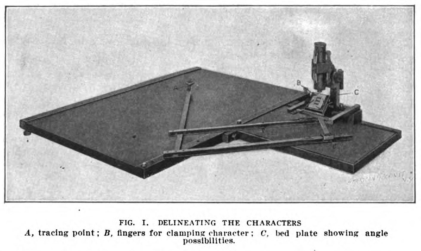
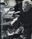
Benton's 1906 description, cited above, is not illustrated. In 1909, however, an article by W. J. Kaup appeared in The American Machinist which did illustrate several ATF (and presumably Benton) pantographs. The first machine illustrated is captioned "Delineating the characters." [5] To the best of my present knowledge, this is the only illustration of this machine, as-built, which survives.
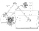
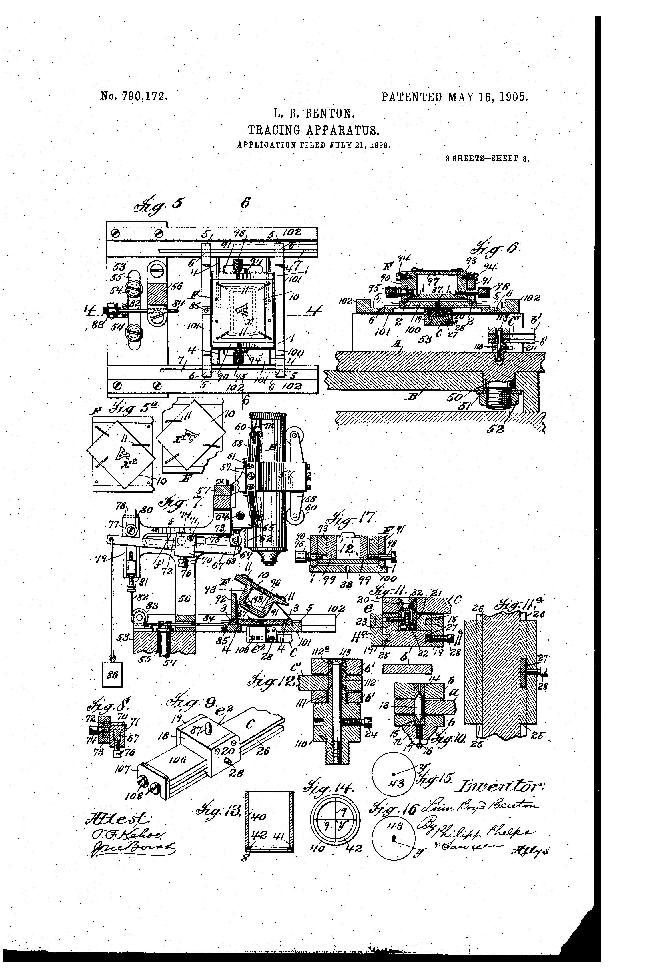
However, this machine is clearly based on the one described in Benton's US patent 790,172 (issued in 1905, but filed in 1899):
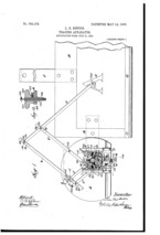
US Patent 790,172
US patent 790,172, "Tracing Appratus." Issued 1905-05-16 to Linn Boyd Benton. Filed 1899-07-21 as application serial number 724,584. Assigned to American Type Founders Company.
This patent is interesting for a number of reasons.
First, it envisions not simply the use of a pantograph to enlarge the drawings prepared by a designer, but also from original sources such as "a print of a type or type-bar [6] This is the only example of which I am presently aware of the direct use of a pantograph to reproduce a type (albeit with an optical tracer). In the later Monotype Corporation (UK) method of turning actual existing type into drawings , for example, optical enlargements were used.
Second, although a version of this machine is shown and described in Kaup's article as drawing on paper only, and although Benton's 1906 description mentions only drawing on paper, the patent itself envisions "a marking or cutting tool of some form acting on a blank ... so as to reproduce the pattern upon the blank..." (US 790,172, p. 1, lines 19-22). It is thus possible that this machine was used in the early ATF method of pantographically incised and hand engraved patterns and that this machine might in fact be the "Benton Delineator" that Rehak mentions in Practical Typecasting , p. 108 (but see note 4 again).
Third, this is just a really clever design from the point of view of pantograph engineering. In most pantographs, one position on the device holds the working tool (e.g., the pencil, or the cutting spindle) and the other end holds a tracer which is guided along a pattern. In this pantograph, there is as usual a working tool at one end. But the tracer end is completely different. Instead of moving a tracer attached to the pantograph's arms over the pattern, the tracer remains stationary and the pattern is moved around it. Moreover, the tracer is not a conventional stylus at all, but an optical device! Benton arranges a microscope at a fixed X-Y position on the tracing end of this device. Crosshairs in the microscope become the "tracer" (there is an added complexity to this to be discussed below). The operator holds the working end of the pantograph (the pencil end, in other words) and moves it so as to move the pattern. By keeping the crosshairs centered on the outline of the pattern, the operator traces an enlarged or reduced version of it.
Using an "optical tracer" of this kind allows the pantograph to work with things which cannot be easily followed physically. An existing type is such a thing: the "face" of the type is the microscopically thin layer of metal at its very top. Below the face, the beard of the type expands at an angle. Tracing the very top of a type - the face - physically would be extremely difficult. Benton's "optical tracer" allows this to be done visually, without worrying about the beard at all.
Fourth, Fifth, and Sixth, the machine has three distinct mechanisms for altering the resulting design so that it is not a simple pantographic enlargement or reduction. So:
Fourth, Simple expansion or condensation of the type design in one direction may be accomplished by tilting the pattern-table which contains the original drawing or type. Visualize the kind of distortion that you get when you view writing obliquely - like the "STOP" painted on a street which appears "correct" when viewed obliquely but which is actually greatly expanded vertically. This pantograph would be used in the opposite way: given an original drawing or type which was "normal," it could be expanded either vertically or horizontally by tilting the pattern-table but still viewing it straight-on from above.
Note: Rotating the pattern-table down can only cause the condensation of a letterform. But if the letterform is drawn in such a way that its "normal" position seen when the pattern-table is already at some angle (45 degrees, for example) then rotating the pattern-table up toward the horizontal from this original angle will expand the design.
Note: The pattern-table tilts in only one direction. To accomplish horizontal or vertical expansion/condensation you rotate the pattern 90 degrees on the table. The resulting drawing is also rotated 90 degrees. This would not seem to present an issue, but Benton designed in to the machine the ability to move the entire tracer mechanism to another side of the drawing board. It isn't clear whether this feature was implemented in the machine shown in Kaup.
Of course, this tilting pattern-table introduces an optical issue: the microscope is focussed on the plane of the pattern-table, but that plane is now tilted. As the pattern-table moves, it will go out of focus. So Benton arranges for the microscope to move vertically as the pattern-table moves horizontally so that it will always remain focussed on the surface of the pattern-table.
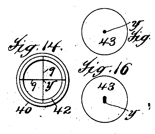
The Fifth major point of interest in this pantograph derives from another problem introduced by the tilted pattern-table, but its solution goes beyond the problem it solves. Tilting the original drawing or type in this way expands or condenses it, true, but it does so uniformly over all of the features of the letterform. Frequently, it is desirable to keep the stems or serifs constant while expanding or condensing the overall letter. Benton accomplishes this by using an optical tracer of greater complexity than the simple crosshair mentioned above.
He allows for a reticle (that would be the modern name for it) in the microscope which may be a crosshair, as above, or may be a round or oblong patch.
This allows him to compensate selectively for the distortions introduced by rotating the pattern-table. An oblong tracer, for example, will expand the resulting drawing more in one direction. This might be used to keep the weight of a slab serif correct while expanding the design vertically, for example.
This feature may also be applied independently of the tilting of the table, of course. Equivalent features were provided as physical disks and other forms mounted on the tracers of Benton's vertical pantographs.
The Sixth major point of interest has to do with the ability of this machine to slant type (Benton says "italicized" and "back-slope," but in more careful terms his "italic" is really just forward slanted type.) To accomplish this one would rotate ("incline") the pattern-table place the pattern or original type at an angle on it. The resulting drawing will also be at an angle on the paper, but Benton allows for the compensation of this by permitting the rotation of the entire tracer side of the pantograph. (The machine shown in Kaup does not have this feature.)
This pantograph is an altogether remarkable machine which does not deserve the obscurity into which it has fallen.
Kaup's 1909 article also mentions the use in reverse of the pantograph he illustrates. This was done to accomodate designs the original drawings of which were large.
"When the original design submitted is large, the machine reproduction is backward, and reproduces it in small form by removing the microscope attachment and in its place attaching a small pencil arm which traces the outline of the letter by moving the long pencil arm over the large outline. This small letter is then filled in solid, that is, leaded, and carefully inspected. This solid leter lends itself more readily to criticism.
There is of course a difference of opinion here in what constitutes the form of a typographical drawing which may be easily judged. Benton (1906) felt that this was best done with enlarged drawings, whiel Kaup (1909) says that small, inked drawings are best.
There is also a potential confusion of terminology here. Kaup says that the "small letter is then filled in solid, that is, leaded". By this I would think he means simply that the small drawing is filled in in "lead" (graphite) pencil. However, in the wax plate method the electroformed shell made from the wax plate is also backed up with "lead" (or typemetal). I am presuming that this is not what Kaup means.
1. Quite possibly both earlier and later; 1899 and 1909 are merely the first and last attested dates from the literature.
2. Curiously, though, the pantograph shown in the photograph of the ATF design room in the 1912 ATF American Specimen Book of Type Styles would seem to be the same machine as the one identified in Kaup's American Machinist article as the wax plate machine.
3. In Hitchcock, Frederick H. The Building of a Book. (NY: The Grafton Press, 1906) . Linn Boyd Benton wrote the chapter on "The Making of Type," pp. 31-40.
4. The terms "delineating machine" and "Delineator" have been used in sufficiently confusion ways in the literature so that I find it preferable to avoid them altogether. In Benton's chapter in The Building of a Book (1906) he refers to a pattern enlarging pantograph, which drew on paper, as a "delineating machine." In this same source, he describes the wax plate process of producing working patterns, but refers to its pantograph as simply "a machine." In the 1909 Kaup article in The American Machinist , the captions of the illustrations refer to "Delineating the Characters" (the design pantograph, writing on paper) and "Delineating on Wax Plate" (making the wax plate for the working pattern). Finally, Theo Rehak, in Practical Typecasting refers to yet a third machine (or at least a third application) as the "Benton Delineator." This machine was used in a different method of working pattern preparation in which the pantograph scribed lines on a "lead" (typemetal?). This was then "firmed up by hand engraving" (p. 108) Benton's 1899/1905 US patent 790,172 for a machine much like the one shown in Kaup envisions a machine which could not only be used for drawing (as in Kaup) but with a "cutting tool." It is possible, therefore, that the Kaup machine is the "Benton Delineator" that Rehak describes. It is also possible that Benton's patent, filed in 1899, simply included in its language a reference to the early ATF method of pantographically incised and hand engraved patterns , just in case.
5. From Kaup, W. J. "Modern Automatic Type Making Methods." American Machinist. Vol. 32 (December 16, 1909): 1042-1046.
6. I believe that "type-bar" as used in this patent means a Linotype slug (not a typewriter typebar). Benton's patent attorney was just trying to be general (so that Linotype couldn't circumvent the patent by using it on slugs, not types). For further discussion of the issues involved in working from existing types, see the two Design Sources chapters on using Existing Metal Types, Pantographically and Existing Metal Types, Optically.
All portions of this document not noted otherwise are Copyright © 2012-2013 by David M. MacMillan and Rollande Krandall.
Circuitous Root is a Registered Trademark of David M. MacMillan and Rollande Krandall.
This work is licensed under the Creative Commons "Attribution - ShareAlike" license. See http://creativecommons.org/licenses/by-sa/3.0/ for its terms.
Presented originally by Circuitous Root®
Select Resolution: 0 [other resolutions temporarily disabled due to lack of disk space]