This Notebook discusses the drawing sizes I use (basically, the dimensions of the frame of the drawing, not the physical or virtual paper size). For actual drawing frames (in DXF format) see the ../ CRT Drawing Frames Notebook.
I use an odd set of sizes for my drawings. Here they are:
And here are the "extended" sizes, intendes for full-scale drawings of relatively large engineering items such as Linotypes (but still not enough for mainline locomotives, aircraft, ships, etc. at full scale). These are essentially digital sizes, and they include sizes for which no commercial paper was ever manufactured.
What follows is a verbose explanation of what these sizes are and why.
In theory drawing sheet size doesn't matter in CAD, because in theory everything stays on the computer where it can be scaled arbitrarily for display. (In fact, in CAD the very idea of a "drawing" breaks down. This is in my opinion a communications flaw inherent in most conceptions of CAD. A drawing is a composed/written/drawn text for communication, while a model is just a model which must be interpreted. From the point of view of communicating technical information, the breakdown of drawing into modeling is a bug, not a feature.) In practice, printed drawings are nice to have, so the intended size of the drawing does matter.
In businesses, engineers have lovely plotters and printers that handle beautiful big sheets of paper. I have home office computer printers, which print US "Letter" size, or A4 at best. Many amateur machinists and "model engineers" (my hobby) have similar equipment limitations. These are made worse in the US by the retrograde nature of US industry (Have you ever tried to buy A4 paper in the US? It is available, if at all, only via mail order.)
I wish to produce drawings which will print well given US home office equipment (on both ISO and US sized paper) yet which themselves take advantage of the sensible theoretical framework of the ISO paper size series. This essay presents the entirely nonstandard drawing sizes I use, with a discussion of the reasons I chose them.
(Note: "crt" is of course simply shorthand for CircuitousRoot.)
There are two reasons to use in drawings the conventions of the ISO 216 standard for paper sizes. Firstly, they're the international standard. This is a matter of compatibility. A drawing prepared on US "Letter" paper (ANSI Y14.1 "B"; 8.5 x 11 inch; 215.9 x 279.4 mm) may not print properly on the functional equivalent (that is, paper for writing letters) in most of the world, A4 (210 x 297 mm). The is true for larger drawings as well. The largest non-metric US drawing paper size, ANSI "E" (33 x 34 inches, 863.6 x 1117.6 mm), is nearly an inch larger in one dimension than the corresponding ISO paper size, A0 (841 x 1189 mm). US paper sizes are unlikely to be available internationally. Model engineering, my hobby, is by its nature international and has its deepest roots in Europe.
Secondly, and more importantly, the ISO paper series is beautifully designed to scale ("scale" as a verb; that is, to be scalable from one size to another). See Marcus Kuhn's excellent essay, "International Standard Paper Sizes" (online at http://www.cl.cam.ac.uk/~mgk25/iso-paper.html ), for a discussion of this.
Briefly, the short and long dimensions of each size are in the proportion: 1:sqrt(2)
Paper so proportioned has the very desirable property that two sheets placed side by side have, together, the same width/length proportions as each sheet individually. Put differently, you can double an ISO paper size and the result is an ISO paper size. Double A4 (210 x 297 mm) and you get A3 (297 x 420 mm). This continues all the way up to A0 (841 x 1189 mm), which is 1 square meter (mathematically, 0.999949, which is very close).
The two Figures below show the ISO "A" paper series from A0 through A8, arranged in two different fashions. Fig. 1 shows them superimposed with a common origin at the lower left. Size A4 is shown in red. Fig. 2 shows that paper sizes form a doubling sequence from A8 (in the lower left corner), to A7 (equal to two A8 sheets side by side), to A6 (equal to two A7 sheets one above the other), and so forth to A0.
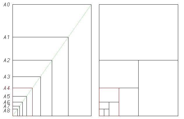
Figs. 1 and 2: ISO A Paper Series
At first this doubling property may not seem significant. After all, it is possible to take any original size and create a series of smaller sizes by repetitively cutting in half. Likewise it is possible to take a small original size and generate a series by repetitively doubling it. Here, by way of comparison, is the ANSI engineering sheet size series (A through E), presented as above. ANSI A size (highlighted in red below) is identical to US "Letter" size (8.5 x 11 inches).
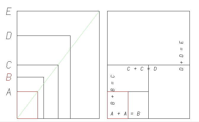
Figs. 3 and 4: ANSI Paper Series
The sqrt(2) sequence used in the ISO "A" series isn't just any doubling (or halving) sequence, though. If you take any ISO paper size and increase one of its sides to match the corresponding side of the next paper size up and then you increase the other side in the same proportion, the other side matches. Thus if you were to take an A4 sized sheet of rubber and stretch it so that its short side matched the short side of an A3 sheet, and you stretched its long side in the same proportion, the long side would match the long side of an A3 sheet.
I've tried to show this in the leftmost example below. The smaller black rectangle represents an A4 sheet. The larger red rectangle is that A4 sheet increased to match an A3 sheet. It's a bit hard to see, since the enlarged A4 sheet matches the A3 sheet exactly.
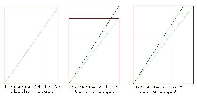
Figs. 5, 6, and 7: ISO and ANSI Doubling
By way of contrast, the middle example above shows what happens if a US letter sized sheet (ANSI A) is enlarged so that its short side matches the next-larger size (ANSI B) and so that its long side is enlarged in the same proportion. The resulting sheet is 11 x 14.2 inches, which isn't at all close to ANSI B size (11 x 17 inches).
It doesn't work to try to enlarge the long side, either. In the rightmost example above, I enlarge the long side of ANSI A / Letter to match ANSI B. The resulting sheet is 13.1 x 17 (not 11 x 17, as desired).
I suppose it isn't worth belaboring this feature much more. Either it will be perfectly obvious to you that this is the coolest thing since fish grew legs, or it won't.
These are the ISO A series paper sizes, in millimeters, from A0 to A8. The area of A0 is designed to be one square meter (mathematically, it is 0.999,949 square meters, neglecting tolerances).
| Name | Short Side | Long Side |
| A0 | 841 | 1189 |
| A1 | 594 | 841 |
| A2 | 420 | 594 |
| A3 | 297 | 420 |
| A4 | 210 | 297 |
| A5 | 148 | 210 |
| A6 | 105 | 148 |
| A7 | 74 | 105 |
| A8 | 52 | 74 |
Tolerances are 1.5 (mm, of course) for dimensions up to 150, 2.0 for dimensions between 150 and 600, and 3.0 for dimensions over 600. This means that two sizes have different tolerances in their short and long dimensions: A1 has a tolerance of 2.0 in its short dimension (594) and 3.0 in its long dimension (841), while A5 has a tolerance of 1.5 in its short dimension (148) and 2.0 in its long dimension (210).
(Aside: I'm not quite sure if these are unilateral or bilateral tolerances, and how they're measured.
It isn't that a paper dimension goes from X to Y (say, 0.0 to 210.0) and we have to decide if each side is toleranced (-2, +0) or (-1, +1) or (0, +2). That would give an overall range of possible ranges from (minimum: +2 to 208 = 206) to (maximum: -2 + 212 = 214). This can't be right.
So I'll assume (but could be wrong; I haven't read the standard!) that the tolerance is a bilateral tolerance applied to the nominal length. Thus: 210 +/- 1, for a minimum size of 209 and a maximum of 211.)
Given the rounding to even millimeters, does the doubling work?
For doubling, it will "work" if the doubled size fits inside the next ISO paper size. For the A8 to A0 range, it does.
Halving doesn't work exactly, though. (Each instance of "extra space" in the doubling procedure corresponds to a problem in the halving procedure.)
Still, the amount that the larger paper is oversized when halved is 0.5mm.
As an example, doubling A5 (148x210) to A4 (210x297) works (see above) and preserves the aspect ratio to the second decimal place (1.4189 for A5, 1.4142 for A4)
Halving A4 to A5 doesn't quite work (again, see above). To reduce an A4 image to fit entirely within an A5 sheet, reduce the short side of the A4 image (210) to fit the short side of the A5 paper (148). The long side of the resultant image is computed by multiplying this by the A5 aspect ratio: (148 * 1.4142 = 209.3), which is less than the 210 length of the sheet. Only about 0.7 mm along the long side is wasted.
(A3 and A4 would be more common, but they work both ways; I wanted to choose an example that didn't work in halving.)
Even at the larger sizes, the waste remains minimal. Halving an A0 image to fit A1 paper results in an image that is 594 x 839.79, wasting about 1.2 mm along the long side of the sheet. This is 1.2 * 841 = 1009.2 mm², or about 1.6 in². By way of contrast, the reduction of a (much smaller) 11x17" image to 8.5x11 wastes (1.36 * 11 = 14.98 in² (about 9,651 mm²).
[Figs. 8 and 9: ISO A Series Doubling and Halving Examples [not yet done]]
Not only do paper sizes scale in this way - so do ISO standard technical pen sizes. (ISO 9175-1) So if you increase size of a drawing to the next A series size, the lines on it just move up to the next technical pen size. This is very cool.
[Fig. 10: ISO 9175-1 Technical Pen Sizes [not yet done]]
Question: what are the tolerances on these?
It is probably true that this is most useful in scaling up rather than scaling down. The lines and features (such as the title box) of a large drawing are smaller in proportion to the drawing than those of a small drawing. Scaling, say, a drawing done on A0 paper down to A4 might result in unprintably small lines. It's still a neat concept, though.
ASME Y14.2M-1992 ( Line Conventions and Lettering) recommends the use of only two widths of lines in drawings, "thin," and "thick." It says that thin lines shouldn't be less than 0.3mm wide, that thick lines shouldn't be less than 0.6mm wide, and that the ratio between the two should be approximately 1 to 2. ISO technical pen sizes 0.35 and 0.70 satisfy these requirments. (The standard further says that CAD drawings can use only one width of line, but this seems to me to be an exception made necessary by limitations in CAD.) This use of the same two line widths regardless of the drawing size doesn't take advantage of the scalability of ISO technical pen sizes.
Prior to 1995, the ANSI (American National Standards Institute) / ASME (American Society of Mechanical Engineers) standard sizes for engineering drawing sheets in the US were those listed as A through F in the table below (note that size F is smaller than size E). These former sizes, while still common, have been superseded by ISO A series sizes with usage as specified in ASME Y14.1M-1995. The ANSI/ASME sizes G, H, J, and K are for rolls, not sheets. The other sizes listed are simply common US sizes. The "legal" size, in particular, is of interest as can be hand-fed through many office printers; it offers just a bit more space than ANSI A-size ("letter") while still being easy to print. In the table below I've put width before height. While it is more common to quote these sizes height-before-width (e.g., 11 x 17), most engineering drawings are landscape format.
(Data from {Madsen 1991}, p. 38 after ASME-ANSI Y14.1 - 1980.)
Roll sizes are given as height x (length min to length max).
Data from {Engineers Edge}. It lists G, H, and K as "not preferred." Size for G confirmed in {Madsen 2012}. Size for J confirmed in {Madsen 1991}.
These are the data for the ISO 2-hole specification [STANDARD NO. ?]:
| Feature | Specification |
| hole size | 6 +/- 0.5 mm |
| distance edge to hole center | 12 +/- 1 mm |
| distance of centers apart | 80 +/- 0.5 mm |
Holes are symmetric around their axes.
For ISO 4-hole, add 2 more holes, 80mm above and below 2-hole system holes
[Fig. 11: ISO Hole Punches [not yet done]
So at the maximum hole size and maximum distance from the edge of the paper, a hole can extend at most (12 + 1) + ((6 + 0.5)/2) = 16.25 mm from the edge of the paper.
Hole punching really applies only to things that are going to be put into binders. That would be mostly A4. I don't know the range of sizes of ISO binders, but I'll assume that it doesn't make too much sense to hole-punch something smaller than A5 or larger than A3. (I suppose, though, that the 80mm center distance means that you could in fact ISO 2 hole punch down to the long side of A7.) So to ensure space for hole punching on either the long or short side of A5, A4, and A3, subtract 16.25, giving maximum usable areas of:
| Paper | Short Side | Long Side |
| A3 | 297-16.25 = 280.75 | 420-16.25 = 403.75 |
| A4 | 210-16.25 = 193.75 | 297-16.25 = 280.75 |
| A5 | 148-16.25 = 131.75 | 210-16.25 = 193.75 |
I couldn't find any specifications for US 3-hole punch size and spacing. It is commonly used on the long side of 8.5x11 inch "letter" paper only (there are other punch conventions for "ledger," computer printout, etc.) "Larger" 9/32 inch (7.1mm) holes seem common now. So I punched a piece of 8.5 x 11 inch paper and measured it. I discovered the following approximate measurements:
[Fig. 12: US Hole Punches (Empirical) [not yet done]
All that matters here is how far a hole projects into the paper. That would seem to be: 13/32 + ((9/32) / 2) = 26/64 = 0.40625 inches (10.32 mm).
Two-hole punching in the US seems completely nonstandard. This has been made more complex because many kinds of sheets have been two-hole punched - not just US Letter / ANSI A.
A bit of searching online indicates that one supplier of binders for two-hole punched US letter paper uses a hole spacing of 2 3/4 inches (presumably centered on the short side of the paper). As binder (not paper/punch) makers, they don't have to specify the hole size. See http://www.bindertek.com/standardbinder.html
I'll use this 2 3/4 inch spacing, then, with a 9/32 inch hole size (the same as the larger holes now common in US 3-ring paper punches). I'll use the same edge-to-hole-center distance as the 3-ring, which is really all that matters for drawing frame positioning.
2-hole, left-side binding seems appealing for landscape format drawings until you realize that while 3-hole binders are cheap (I get them secondhand at the St. Vincent de Paul "Dig and Save" for 35 cents/pound) 2-hole binders are almost freakishly expensive ($11/each for a 2-inch thickness). It would seem that they're mostly used by lawyers, and this is only 2.2 minutes' worth of time for a mid-range attorney.
I'll be printing much of what I draw on an ordinary consumer-grade laser printer. These printers can't always print right up to the edge of the paper. This unprintable amount depends, of course, on the particular brand of printer. I measured one printer available to me, and discovered:
| Side | Unprintable (mm) |
| Bottom | 6 |
| Right | 4.5 |
| Top | 2.5 |
| Left | unmeasured |
The old rule of thumb that I recall hearing was 1/4 inch (6.4mm) on each side; clearly this printer does a little better.
Still, to be on the safe side, I'll adopt an unprintable margin (which might contain part of the Zones) of 6.35mm (1/4 inch).
For A4 and US 8.5 x 11 inch paper, this combines with the hole punch margins to give the following maximum usable area:
[Fig. 13: Combined Printing and Hole Punch Margins [not yet done]
"Zones" are lettered and numbered areas along the edge of a drawing which allow rapid (X,Y) reference to specific areas of the drawing. They're like the letters and numbers along the edges of a road map.
Zones are defined to be in the margins of a drawing (ASME Y14.1M-1995). The standard makes an exception for drawings on A4 paper; these may or may not have zones.
[Fig. 14: ASME Y14.1M-1995 Zones [not yet done]
In the paper sizes I'll define below, these zones may or may not print on printers which cannot print right to the margin. The sizes, especially crt4, are already small enough; to reduce them further by ensuring that zones are within printed margins is something I don't wish to do.
The drawing sizes I'll adopt are proportioned in the same 1:sqrt(2) ratio as the ISO paper sizes, but are reduced in size so as to print on either the ISO sized paper sheet or the US sized paper sheet which roughly corresponds to each drawing size.
To create these drawing sizes, I designed my A4/US Letter/ANSI "A" equivalent, "crt4," first and then worked up and down to make sure that the other sizes would fit, especially given punching allowances and margins for printing. I discovered that at crt2 (A2, ANSI "C") margins cease to become an issue; they're pretty large. At crt5 (A5) and below, there are no real punching standards, and the area is within the printable size of a standard home/office laser printer, so margins are calculated but ignored for ISO A series printing, and completely undefined for US paper printing.
To design crt4: A4 is 210 x 297 and US Letter is 215.9 x 279.4. So, inconveniently, my short side limit is set at 210 (from A4) and my long side limit at 279.4 (from US Letter). As noted in the Printing Margins section earlier, the maximum usable short-side dimension for A4 is 187.4 mm and the maximum usable long-side dimension for US Letter is 262.74 mm.
If I multiply the short-side maximum (187.4) by sqrt(2), this would give 264.5 for the long side, which is too long (exceeds 262.74, US Letter maximum). I then tried to reduce this to 185mm, which gives 263.63 (or 262) on the long side. This would fit on the paper, but wouldn't allow hole punching arbitrarily on either side (and when crt3 was generated from it, wouldn't allow hole punching on the long side). So I reduced the size to 181 mm. This gives 256 mm for the long dimension, which has an aspect ratio of 1.41 and which fits within all punching and printing margins. (It also means that the long dimension of crt0 will work out to be 1,024 - a nice number for a programmer, but entirely accidental.)
So my basic size is crt4: 181 mm x 256 mm.
Fig. 15 below shows this series working up from the smallest size (crt8), each size doubling the one before it (but all having approximately the proportions 1:sqrt(2)).
Fig. 16 below shows the series superimposed.
I should also be noted that these drawing sizes are not guaranteed to be Y14.1 compliant.
It is both sensible and convenient in digital drafting to draw everything at full scale. The computer doesn't care how "big" the drawing is, and it can always be scaled for printing/plotting to whatever size device is available.
In my own work, the largest things I expect to be drawing (excluding buildings, which can be handled separately) are Linotypes (the Barth Type Casters come close). The largest non-Rangemaster Linotype was the Model 30 (mixer, with size magazines). Overall, it was roughly 90 inches wide, 62 inches deep, and 83 1/2 inches tall. The Rangemaster equivalent (the Model 36 - the largest Linotype ever made) would have been slightly larger, but I do not have dimensions for it.
So the largest engineering drawing I'm likely to need to make is a three-view General Arrangement drawing of a Model 32 or 36 Linotype. If I scale the "crt" sizes up (which drives their numbers down into negative values) I get:
(Technically the crt -6 8192 dimension should round to 8193, but I like 8192 better.)
The largest of these sizes, which works out to a bit more tha 26 feet wide by 19 feet high, should accomodate easily a General Arrangement drawing of a Model 36 Linotype at full scale.
The primary flaw with the numbers of this series is in the crt6 size (91 x 128). Doubled, it gives 182 x 256, which is 1 mm wider than crt5 is long. With repeated duplication, this flaw continues. Thus 4 crt6 pages are also 182 mm wide, 1 mm wider than crt4 is wide. 16 crt6 pages are 364 mm wide, 2 mm wider than crt3 is long. 32 crt6 pages are also 364 mm wide, 2 mm wider than crt2 is long. 64 crt6 pages are 728 mm wide, 4 mm wider than crt1 is long. Finally, 127 crt6 pages are also 728 mm wide, 4 mm wider than crt0 is wide.
All other sizes double within the bounds of the next larger size.
Halvings work exactly from crt0 through crt5. crt5 (128x181) halved (= 128 x 90.5) fits within crt6 (91 x 128). The only halving that doesn't work is crt7 (64 x 91) halved (= 64 x 45.5) to crt8 (45 x 64).
Two flaws isn't bad for a system which rounds to integral millimeters. The ISO A series has five flaws, though none of them are in doubling. Both of the flaws in the crt series are in the under-crt4 range, and thus in the range used by me primarily for boxes around illustrations rather than for drawings I plan to scale.
[Fig. 17: Flaw - crt6 Doubling [not yet done]
[Fig. 18: Flaw - crt7 Halving [not yet done]
The "crt" sizes are drawing sizes, intended to be printed on physically available sheet sizes (such as A4, US Letter, etc.) Thus the margins on the crt sizes are on the outside of the drawing dimensions; they are not further subtractions within the drawing dimensions. Note that margins on sizes crt4 and larger which contain technical drawing frames may not in fact be blank, but may contain "zone" information. Of course, this zone information, being in the margins, may or may not print properly and may or may not be punched through.
The diagrams below show the crt sizes from crt4 up to crt2 superimposed on the corresponding A series or ASME sheet, with hole punches indicated at maximum tolerance values for the system appropriate for the sheet. The unprintable-area margin is shown by a light green line.
[Fig. 19: crt0 on A0 and ANSI E [not yet done]
[Fig. 20: crt1 on A1 and ANSI D [not yet done]
[Fig. 21: crt2 on A2 and ANSI C [not yet done]
[Fig. 22: crt3 on A3 and ANSI B [not yet done]
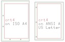
Drawing size crt4 fits on A4 such that it may be centered on the long side (and yet leave room for punching either short side). It must, however, be offset in the short direction so as to miss punches on the long side. On ANSI A / US "Letter," it may be centered in both directions and will miss the punches on the long side. (Short-side punches are undefined for this sheet size, but it would probably hit them if they were there.)
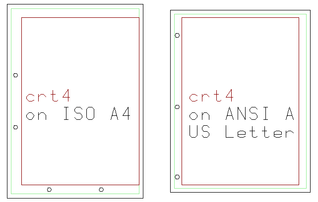
Fig. 23: crt4 on A4 and ANSI A / (US "Letter")
[Fig. 24: crt5, crt6, crt7, and crt8 [not yet done]
By way of contrast, ANSI/ASME drawing sizes are sheet sizes, so their margins must be subtracted from their dimensions. Here are the ASME Y14.1M-1995 drawing sizes with minimum margins
| name | sheet short | sheet long | margin | drawing short | drawing long | drawing aspect ratio |
| A4 | 210 | 297 | 10 | 190 | 277 | 1.46 |
| A3 | 297 | 420 | 10 | 277 | 400 | 1.44 |
Margins on theoretically perfectly sized paper are the sum of the left and right (or top and bottom) margins. If the tolerances of the paper sizes for the ISO A series are taken into account, these tolerances must be added to the margins (making the margin large enough to accomodate the smallest in-tolerance paper). Tolerances for US paper are undefined, and so are simply ignored here (hoping for the best). The drawing may be positioned anywhere within these margins, as appropriate for hole punching, printing margins, and aesthetic balance.
For sizes from crt4 through the short side of crt1 on ISO A series sheets, each combined pair of margins must exceed: one side punching allowance + one side nonprinting allowance + sheet tolerance, or 16.25 + 6.35 + 2 mm = 24.6 mm. For US paper sheets, each combined pair of margins must exceed one side punching allowance + one side nonprinting allowance, or 16.25 + 6.35 = 22.6mm, plus some luck for sheet tolerance.
For sizes from the long side of crt1 through crt0, each combined pair of margins must exceed (16.25 + 6.35) = 22.6 mm + 3 mm = 25.6 mm (A series) or 22.6 mm + luck (US paper).
The crt4 through crt0 sizes meet these criteria.
For sizes crt5 and below, margin calculations are less meaningful. In the drawing size table earlier, margins for ISO printing are computed. Margins for sizes crt5 and below for US paper sizes are undefined as there are no standard US paper sizes in this range. However, crt5 and smaller sizes aren't going to print in a standard way through a home/office printer, so these margins need not equal or exceed the computed minimum (16.25 + 6.35 + 1.5 = 24.1 mm for these sizes) as must the larger sizes.
The sizes, especially crt4, are already small enough; to reduce them further by ensuring that zones are within printed margins is something I don't wish to do.
(In the digital formats (camera, computer screen) I'm assuming that pixel spacing is identical in the horizontal and vertical directions. In reality this may not be so.)
For discussions of European and Japanese business card sizes, see:
http://www.cl.cam.ac.uk/~mgk25/iso-paper.html and http://home.inter.net/~eds/paper/dtpofficepaper.html
These sources note that international business card sizes vary, but are often ISO 7810 ID-1 (85.6 x 53.98 mm) (aspect ratio: 1.59) or A8 (74x52). I don't yet understand the derivation of the ISO 7810 ID-1 size.
Here's the Varkon MBS source for the Figures used here. They were (on my system; this is for my reference) in a project called "paper" which had an Active Module which simply called "driver.M". This looked something like this:
global module driver();

include(CrtCommonTerms.h)
include(CrtDrawingSizes.h)

include(CrtPaperPenISO.h)
include(CrtPaperPenOther.h)

beginmodule

!csys_1p(#1,"iso_a_1",vec(0,0,0): BLANK=1);
!part(#2,fig_iso_a_series_1(),#1);
!csys_1p(#3,"iso_a_2",vec(ISO_A0_short * 1.1,0,0): BLANK=1);
!part(#4,fig_iso_a_series_2(),#3);

!csys_1p(#10,"ansi_1",vec(0,0,0): BLANK=1);
!part(#11,fig_ansi_series_1(),#10);
!csys_1p(#12,"ansi_2",vec(ANSI_E_short * 1.1,0,0): BLANK=1);
!part(#13,fig_ansi_series_2(),#12);

!csys_1p(#20,"iso_ansi",vec(0,0,0): BLANK=1);
!part(#21,fig_iso_a_ansi_doubling(),#20);

!csys_1p(#30,"crt4",vec(0,0,0): BLANK=1);
!part(#31,fig_crt4_on_a4_a(),#30);

endmodule
Everything here is quick-and-dirty. This is ugly code. It certainly won't install as a cleanly compiling system. I'm just stashing it here so that I won't lose it and will have something to work from should I ever redo this Notebook.
{Engineers Edge} "Engineering Drawing Inch Format Sizes." Web page on the Engineers Edge website, at: http://www.engineersedge.com/engineering_drawing_formats/engineering_drawing_format_sizes.shtml Accessed 2014-11-17.
{Madsen 1991} Madsen, David A., Terence M. Schumaker, J. Lee Turpin, and Catehrine Stark. Engineering Drawing & Design. Clifton Park, NY: Delmar, 1991.
This source is useful because it reprints the illustration of "STANDARD DRAWING SHEET SIZES" from ASME-ANSI Y14.1 - 1980.
{Madsen 2012} Madsen, David A. and David P. Madsen. Engineering Drawing & Design. Clifton Park, NY: Delmar / Cengage Learning, 2012.
These are the notebooks of a hobbyist who has no professional qualifications in drafting. Please see the "Drafting and Me" Notebook for an explanation and disclaimers.
All portions of this document not noted otherwise are Copyright © 1998, 2002-2003, 2007-2008, 2014 by David M. MacMillan and Rollande Krandall.
Circuitous Root is a Registered Trademark of David M. MacMillan and Rollande Krandall.
This work is licensed under the Creative Commons "Attribution - ShareAlike" license. See http://creativecommons.org/licenses/by-sa/4.0/ for its terms.
Presented originally by Circuitous Root®
Select Resolution: 0 [other resolutions temporarily disabled due to lack of disk space]