This Notebook presents DXF-format files containing blank drawing frames for the use in CircuitousRoot projects. The frames use the unusual (but probably ANSI/ASME Y14.1 compliant) "crt" drawing sizes.
If you want to use these for your own work, go ahead. All of the ones published here are placed by me in the public domain; these are generic versions. (I use versions with "Circuitous Root" filled in for the Organization Name in my own work.) I doubt, though, that these will be very useful for you - my own conventions, and the "crt" sizes, are just a little too strange. Please note as well that while I refer to standards often in the creation of these drawing frames, they should not be assumed to be standards-compliant. As I note in the boxed legal notes section at the end of this web page, these are the notebooks of a hobbyist who has no professional qualifications in drafting. Please see the "Drafting and Me" Notebook for an explanation and disclaimers.
The title blocks and other information blocks on these drawing frames are simplified considerably from commercial practice. They're appropriate to a one-person hobby / home-shop environment, which is what I'm using them for. In particular this means that there are no fields for checking and approval. Note also that I've considered and rejected the idea of multi-sheet drawings. Each drawing is a single digital sheet which has a single drawing number and which resides in a single file.
About units: Unlike most of my compatriots, I rather like the metric system. The US should have adopted it a century or more ago; the arguments against it are just as stupid today as they were when they were first made in the 19th century. The only difference is our delay has been unimaginably costly. But despite this I've gone to some length to establish inch-system drawing layouts. Why? The reason is that I'm not engaged primarily in the drawing of new things, but rather in the documentation of old machinery. Most of this was developed in the inch system. Indeed, some of it requires measurements in other systems entirely. I'm a typefounder, so my machinery has many dimensions which are properly expressed in printers' points and picas. Mechanical watches still make reference to the pre-Revolutionary Parisian ligne. The conventions used in drawing an old machine for preservation should match those used in its original creation.
The "crt" drawing frame sizes are explained in ../ The "crt" Drawing Sizes Notebook.
See ../ The "crt" Drawing Sizes -> Hole Punching Considerations for data on hole sizes and positions. Before adopting a 2-hole punch system, investigate the cost of the binders for it.
See ../ The "crt" Drawing Sizes -> ISO Technical Pen Sizes for the pen sizes underlying metric line widths.
Line widths are defined by ASME Y14.2 ( Line and Lettering Conventions). This standard defines two widths: "thick" and "thin." These should have approximately a 2:1 ratio to them. (But note that earlier US military standards may require "thick," "medium," and "thin").
Y14.2-1979, as cited in {Madsen 1991}, specifies 0.032" and 0.016" approximate widths for inch-format thick and thin lines, and 0.7 mm and 0.35 mm for metric thick and thin lines. These metric widths are ISO standard sizes (ISO/DIN 128 1977, ISO 9175-1), and not conversions from the inch widths (0.7 mm = 0.028", not 0.032"). The metric widths (0.7, 0.35) correspond with ISO technical pen sizes.
Y14.2M - 1992 and the Y14.2-2008 (the latter of which is the current version as I write this is 2014) specify different widths for metric thick and thin lines: 0.6 mm and 0.3 mm. These don't make any sense at all, either as ISO technical pen sizes or as soft conversions from Y14.2 - 1979 inch sizes. Yet they've been the US standard for over two decades now.
I'll use the Y14.2 line conventions for the drawing frames, but reserve the right to use other and earlier (even 19th century) conventions for the drawing frame block contents and for the drawings themselves.
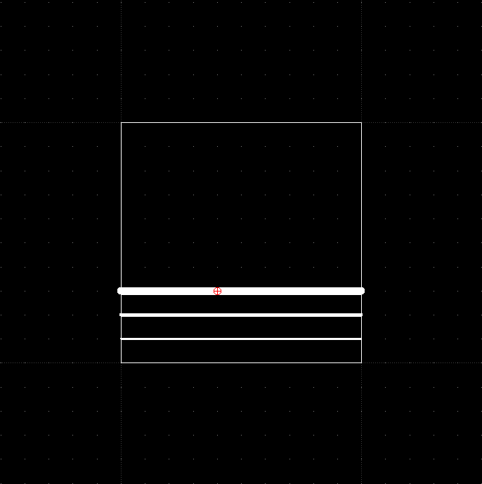
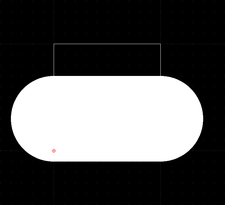
LibreCAD does not work with dimensioned entities. Instead, it works with undimensioned entities and applies a dimensional interpretation to the entire drawing. This means that if you set up a drawing in inches, and draw some stuff, and then change the dimension system for the drawing to millimeters, all of the non-zero-dimension entities become huge blorbs.
For example, each of the two images below is a screengrab of the drawing librecad-inch-to-mm-conversion-example.dxf On creation, I set the dimensional system for this drawing to inch. Then I drew a 1-unit (1-inch) square box with zero-dimension lines. (These, as you can see, did not change.) Within the box I drew three horizontal lines at three different thicknesses. (0.2 mm, 0.4 mm, and 0.8 mm; even in inch mode you can only draw metric-width lines in LibreCAD, but they turn out as soft conversions to inch widths ... got that?) Then I went to the Edit -> Current Drawing Preferences menu item, selected the "Units" tab, and set the current drawing units from inch to millimeter. The image on the right was the result.
I do not know if this is a bug in LibreCAD or in the DXF format (I suspect the former). But until it is resolved, it is not possible to switch the unit system for a document after you start drawing things.
The upshot of this for drawing frames is that you must have separate inch-system and mm-system drawing frames for (respectively) inch and mm drawings, even if your two frames are visually identical.
To convert an inch-system drawing to millimeters, first use the Modify -> Scale operation to scale the entire drawing (use Select -> All) up * 25.4. This gives you 25.4 units for each 1 unit of the original drawing. Then go to Edit -> Current Drawing Preferances -> Units and change the drawing dimensions to millimeters. (I won't take the time to show it here, but if you do this with the example above you end up with a drawing visually identical to the original.) To go the other way, scale * (1/25.4).
In paper-based drafting and illustration, scaling was necessary - you can't fit a full-size drawing of a Linotype on even an E-size print. But in digital drafting and modeling scale is neither necessary nor advantageous. It's much simpler just to draw everything full-size and then to scale the printed output to fit the paper at hand (if you even print it, which is less and less common).
The "crt" series of frame sizes are intended to assist with this. Because they use the same sqrt(2) scaling as the ISO paper series, drawings of one size can always be reduced to fit nicely within another size in the series.
So my practice will be to draw and model everything at full size, digitally.
One question which this practice raises, though, has to do with the initial size to use for those elements on the drawing (or illustration) which have no natural size and which do not necessarily scale: the title and other blocks of text. For the smaller sizes (ANSI A/B, ISO A4/A3) this isn't really a problem - A/A4 output is readily available, and B/A3 isn't too far off. But what about a drawing intended full-size for ANSI E or ISO A0 (crt0)? If you make the Title Block really the same size as that of a smaller drawing (say, with 0.24" / 6 mm high lettering) then when you scale it down to A/A4 size for printing you won't be able to read a thing. But if you make the Title Block so that it will be legible when scaled down for output, it'll be very large at full size (about an inch high). The problem only becomes worse in the extreme cases - say, a General Arrangement drawing of a Linotype done on the "crt -6" size. This is a virtual drawing size which is 27 x 19 feet. Proportionally, "full size" lettering on the (digital) drawing would be over 7 inches high.
At present I haven't worked through enough examples to really understand how this should work. I'll update things here when I have a better sense of what works.
(Aside: It would be interesting to see what was done in pre-digital locomotive, shipbuilding, and aviation practice. I don't yet have that information.)
These are LibreCAD-generated DXF files for ANSI A-size sheets in landscape (horizontal) format, with inch units set as the drawing unit dimension. I used them as preliminary stages in generating the crt4 drawing frames; they may or may not be useful elsewhere.
[NOT DONE - it's perfectly possible to have ANSI A digital sheets set up for work in millimeters. Indeed, if you're working in the US where ANSI series paper is the only affordable option, but doing metric drawings, you must.]
I'll cover this case in greater detail than later ones, as it establishes many of the basic conventions.
The files here implement crt4 drawing frames on the digital ANSI A size sheets described earlier. The drawing frame is positioned so as to allow for an ASME Y14.1 compliant margin overlaying the nonprinting margins of most printers and also positioned so as to allow two-hole binding on the left side and three-hole binding on the top side.
Note: If you look very closely at the drawing after inch-to-mm conversion, it appears that the border lines do not actually quite reach the crt4 mathematically defined borders. I'm not sure if this is a bug in LibreCAD rendering (which presumably will disappear later) or in its conversion (in which case the problem will remain). The error is small enough that I'm ignoring it, though.
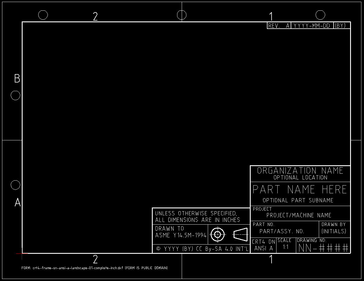
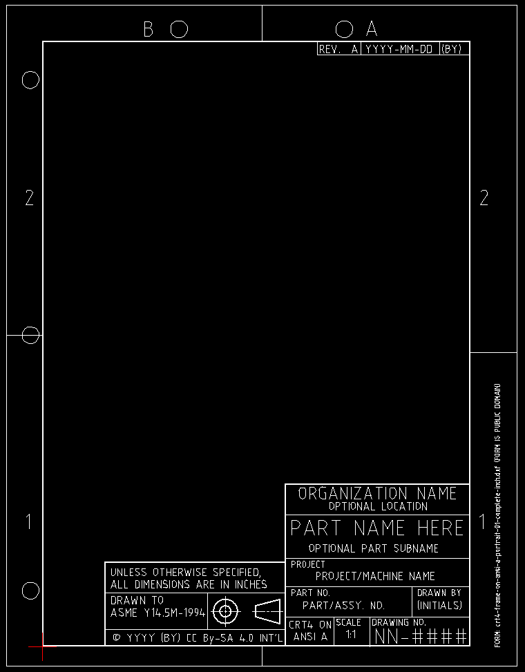
Here's a screengrab of the generic version of the complete inch-system drawing frame (the lines in a screengrab will show up better on a web page than the lines in an exported image):
The visual indications of the punched holes can be turned off by blanking the LibreCAD "0" layer. The visual indication of the ANSI A-size sheet edges can be turned off by blanking the "ANSI A Sheet" layer, but it should probably be left on because it helps LibreCAD position the drawing properly on the sheet (see below, in "How to Print It...")
I've omitted the Zone letters on the right-hand size because unless they're made smaller than ASME Y14.2-2008 specifies (0.24") they get cropped off in the non-printing area of the printer (which, confusingly, makes a 'B' look like an 'E').
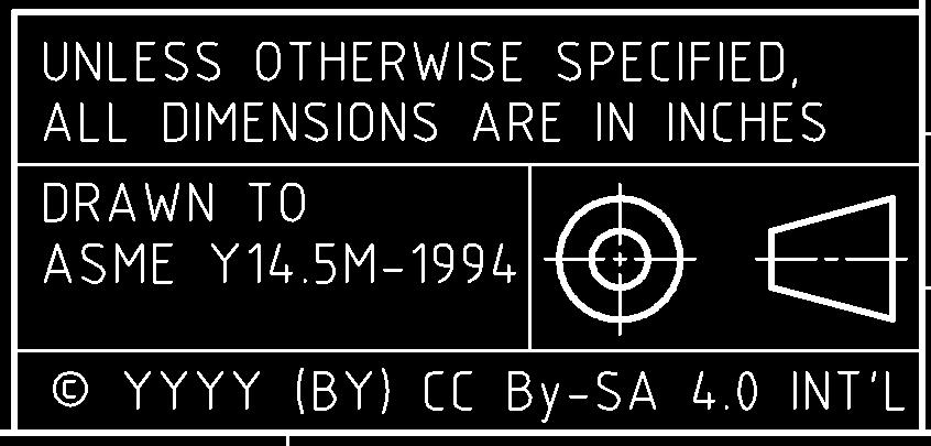
Dimension/Projection/License Block
This block can be turned off by blanking the "Dim./Proj. Block" layer. It contains the ASME Y14.5 requirments that (a) the standard at a specific version be referenced and (b) a general dimensional unit note be included. There's room to add a reference to an additional standard if necessary. It contains the conventional third-angle projection symbol; a first-angle projection symbol is left as an exercise to the European reader. Finally, it contains a line which should be altered to state the current year (replacing "YYYY"), the initials of the copyright holder (replacing "(BY)"), and the license intended (if other than the Creative Commons Attribution-ShareAlike 4.0 International license).
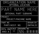
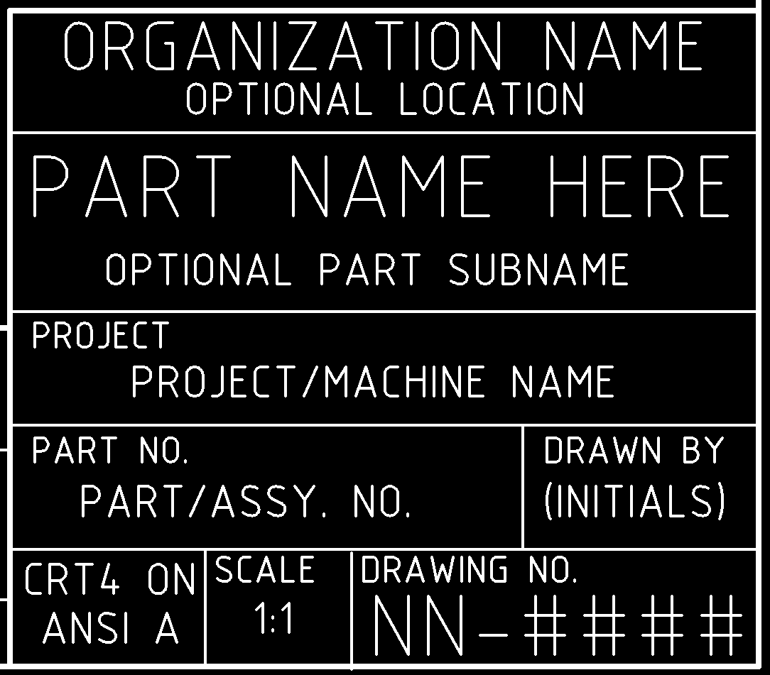
While it is possible to blank the title block level, it isn't likely to be useful to do so (if you need an illustration frame, they're done separately). The title block contains the conventional Organization, Part Name, and Drawn By fields. It adds a "Project" field. This is important in the way I organize my own work, but isn't really standard.
Y14.2 does not explicitly address the lettering in the "Organization" field, except insofar as it might come under the "all other lettering" category. It's common enough to have an organization logo in this place. So while the lettering in the generic example is Y14.2 compliant, I may well change this when I use it for CircuitousRoot drawings. (In particular, I won't restrict myself to uppercase, and I'll make the location name smaller.)
I also make a distinction between the Part No. and the Drawing No. Each Drawing, as I make them, has its own unique number identifying it as a document. This is distinct from the part or assembly it documents. To take a medium-complex example, for a single part number (such as the 47TC1 Vertical Mold Blade of the Thompson Type-Caster) I might have two separate Projects (say, one to document an existing part and another to specify a part for new manufacturing). Each of these situations could require any number of Drawings - but they'd all be of a 47TC1.
I have no field for a Sheet number, as my own convention is never to do multi-sheet drawings. (Each drawing has its own unique number.) The scale is probably redundant, as I always draw 1:1 at the computer; I may remove this field later. The final field identifies the drawing frame and sheet size. There is no "Date" field because I put that in the revision block (the "REV. A" is the original version of the drawing).
There are many fields commonly present in engineering drawings which aren't used here. In particular, I have no "checked" or "approved" fields, since it's just me. Notes for things like Material and Finish should, in my opinion, go on the drawing itself.
The initial entry in the Revision Block (by default "REV. A", although you can certainly change this) is intended to be the initial version of the drawing. (It's the computer programmer in me: If you have an original X, and then a revision of it Xa, then Xb, etc. the series (X, Xa, Xb) has a non-uniform format. Essentially you have a null version level for the first version. This is like fingernails on a chalkboard.)
Whether you duplicate the Revision Block for REV. B, etc. or simply update the information in it to specify the current revision level is up to you. I'll be doing the latter. Retaining multiple revision information on a single sheet made sense with paper drafting, but with digital drafting one ought to be able to rely upon the filesystem (or, better, a proper revision control system).
Much to my surprise, this sheet actually prints perfectly on 8.5 x 11 paper when printed from LibreCAD. There are two tricks, though. You must select "Print Preview" and set the output ratio to "1:1". You must also click on the "Center to page" button in the Print Preview screen. Then the ordinary Print function works properly (or does for me).
Hole placement determines margins:
Hole size is 9/32". Distance from the edge of the sheet to the middle of the hole is 13/32". So the distance from the edge of the sheet to the inside of the hole is (13 + 4.5)/32 = (26 + 9)/64 = 35/64 = 0.55" (approx.) I'll round this up to 0.6". This establishes the border for the left and top sides. It exceeds the minimums defined by Y14.1-1980 (which are 0.25 left/right sides, 0.38 top/bottom sides).
The crt4 drawing frame size is 181 x 256 mm. I'm assuming that a drawing for an ANSI sheet size will be dimensioned in inches, so I'll approximate the crt4 frame size as 7.13" x 10.08".
So the left margin (0.6) plus the horizontal size (10.08), gives a right margin of 0.32". This exceeds the Y14.1-1980 minimum of 0.25.
The top margin (0.6) plus the vertical size (7.13) gives a bottom margin of (8.5 - (0.6 + 7.13) = 0.77. This exceeds the Y14.1-1980 minimum of 0.38.
(But note that according to {Madsen 2012} the current Y14.1 specifies 0.5 inch margins for all inch drawing sizes. If this is true (I haven't doublechecked), then these drawing frames would not be compliant with the current Y14.1.)
In the DXF files, the origin (lower left corner) of the drawing frame is at (0,0). The sheet is offset to (-0.6, -0.77). I'll draw the thick border line for the drawing frame so that it is fully inside the crt4 drawing frame. It would fit in the margin outside without exceeding Y14.1, but drawing it inside keeps the crt series principles intact. (The outline around the A-size sheet is drawn as a minimum-width line, 0.01mm.)
The the hole outlines (which are not really necessary) are in the default level "0" of the LibreCAD drawing. You probably want to blank this level before printing.
The ANSI A sheet outline is in its own level, "ANSI A Sheet". You probably want to leave this level visible as it is used during printing by LibreCAD to figure out where the drawing goes on the actual sheet. (The zone markings, which I've put even on this A-size drawing, run to the sheet edges. They may accomplish the same thing, or they may not. as LibreCAD can't do square-ended lines, I've pulled back their outer limits by half a line width to ensure that they don't project beyond the sheet - but if the print scaling were to use the nominal endpoints rather than the rounded ends, it wouldn't see them going to the edges of the sheet.)
The crt4 frame itself, with all associated blocks, is in its own level ("crt4 Frame").
Zones are optional on A-size drawings according to Y14.1. I've put them here just to do it. The zones are in their own level, which allows them to be blanked easily. Zones are established relative to the sheet size (not the drawing frame size). They're numbered right-to-left horizontally and lettered bottom-to-top vertically.
The letters for the vertical zones are much closer to the drawing frame border than I would like. This is so that they will not fall into the nonprinting area around the edge of the sheet.
LibreCAD presents problems with regard to line widths, because at present (2014, version 2.0.6) it only allows metric widths. (I investigated using DraftSight instead, but I can't get it to reliably handle line widths in real-world units at all, even though it claims to do both inch and metric.)
Formerly ASME Y14 employed different (but similar) line width definitions for inch vs. millimeter drawings. For example, ASME Y14.2M-1979 recommends two sizes of lines to be used: 0.32" or 0.7 mm for thick and 0.16" or 0.35 mm for thin.
ASME Y14.2-2008 and Y14.2M-1992 before it) recommends two sizes of lines to be used, which should bear an approximate 2:1 relationship to each other: 0.6 mm for thick and 0.3 mm for thin. (It mentions only metric widths. 0.6 mm is approx. 0.024" and 0.3 mm is approx. 0.012".) It also allows a single weight for CAD, but I'll ignore that as it is the result of the physical limitations of pen plotters.
I'll use the Y14.2-2008 standards of 0.60 mm and 0.30 mm for the drawing frames. (I may or may not use them for the drawings themselves.)
LibreCAD also presents a second problem with lines because it does not (yet, I hope it later will) allow square line ends which actually end where you say the line ends. Instead, lines end in a half-circle which extends half the line width beyond the actual line end point. This becomes quite apparent when you offset the lines half their width inward to keep the drawing frame inside the crt4 limits - the lines look like they cross at the corners. So I have to adjust the line end locations by half a line's width to at least make these circles merely overlap at the corners. This gives a corner which is rounded (not crisply square); this is wrong, but at least looks better than a log-cabin crossing at the corners. (N.B., with proper 19th century drafting tools you can make square-ended lines and square corners.) All oher lines are drawn centered on their nominal locations.
ASME Y14.2-2008 ( Line Conventions and Lettering) specifies minimum lettering heights (you can go larger if you wish). These are measured either baseline-to-cap-height or x-height to descender-depth. This means that for uppercase-only lettering, the overall letter height is the minimum letter height. But for lowercase or mixed-case lettering the overall letter height must be greater than the specified minimum ( both baseline-to-cap-height and x-height-to-descender-depth must each be at least the minimum letter height. This style of definition works easily when one is lettering by hand: draw your horizontal lines and letter relative to them. It makes things difficult when using digital lettering fonts, however. Fortunately, the lettering style in the standard is suggested, not normative. (N.B., the lettering font called "standard" which comes with LibreCAD seems to be compliant.)
The minimum sizes for inch-system drawings are specified in Y14.2 Table I-1 in Mandatory Appendix I. However, in the latest (-2008) revision of the standard there is a problem.
In ASME Y14.2-2008, the specification for the drawing title, drawing size, drawing number, and revision letter if used in the title block, are, in the standard, completely ambiguous. Really, they are - the standard cannot be rightly interpreted. This is a terrible state of affairs for the most recent revision of a basic component of such an important standard.
The earlier Y14.2-1992 standard contains a better-formatted table which can be unambiguously interpreted. It says that for drawings on sheet sizes A, B, C, and G one should use minimum 0.12" high lettering for these elements, while on drawings on sizes D, E, F, H, J, and K one should use 0.24".
This is probably what the Y14.2 committee still meant when they approved the 2008 revision of this table, but note that it isn't actually what the 2008 version says (it associates both sizes, 0.12" and 0.24", with all sizes of sheets - yes, really; read the table and look at the commas!)
So for this aspect of these drawing frames I'll adopt Y14.2-1992.
For other lettering, both Y14.2-1992 and Y14.2-2008 specify minimum sizes which apply to all sizes of sheets (whew!)
For Section and View letters on the drawing are minimum 0.24". Zone letters and numerals in the borders also are minimum 0.24".
Drawing block headings are minimum 0.10". (I believe that "drawing block headings" are the smaller lettering which labels the contents of the Title and other blocks.)
Finally, all other characters are minimum 0.12".
Exception: The "Form:" line is not really a part of the drawing and does not necessarily comply with any standard. It is, pretty obviously, simply the filename of the DXF file.
This drawing frame is similar in most respects to the landscape version, save that it is in portrait orientation (obviously) and that the three-hole punches are on the left and the two-hole punches on the top. (In consequence the Zone letters are omitted at the bottom, which is too narrow to hold them.)
(See the inch-mm cautionary note, above for more information on the (lack of) exactness in the millimeter version.)
Here's a view of the inch-system version:
(See the inch-mm cautionary note, above for more information on the (lack of) exactness in the millimeter version.)
An engineering drawing, such as those the frames for which were shown earlier, must be capable of functioning as a standalone document; each drawing needs full identification information. By way of contrast, an illustration is typically used within a larger document. A full Title Block and its detailed information would just get in the way if used on each illustration. (When illustrations are used standalone, they tend to be used in a more "artistic" manner - and again a full engineering-drawing style collection of information would clutter things up.) The illustration frames presented here are, consequently, very much simplified.
The Title Block (which is on its own level, and can be blanked) contains just the name of the drawing and a figure number.
The block at the top of the drawing is a "reference" block which can be used to link the drawing back to is primary treatment in the text. This isn't always possible or necessary, so it's in its own level (which can be blanked).
Other than that, it's just a regular crt4 ANSI A sheet. You can blank the hole punch indications by blanking the LibreCAD "0" level. You can blank the "ANSI A Sheet" level to remove the sheet outline. If you're going to print to a single ANSI A sheet, you should probably leave this visible (LibreCAD uses it to fit the illustration to the sheet); if not, it is probably best to blank or remove it.
The format of the Title and Reference blocks here is loosely based on that used in the British Air Publication 564B, C, and D, Hurricane IIA, IIB and IIC Aircraft, Merlin XX Engine [etc.]. (Actually, most of the illustrations in it are in portrait format, so the portrait version of this illustration frame, below, most closely resembles it.) This material hs been reprinted in:
Tanner, John. Ed. The Hurricane II Manual. R.A.F. Museum Series, Vol. 2. London: Arms and Armour Press & NY: Hippocrene Books, Inc., 1976.
The "Hurricane" is of course the Hawker Hurricane aircraft in production from 1937 to 1944.
If one desires to put a logo in the illustration, it seems to me that the best practice might be to include it in the drawing itself rather than in a block. This was the style adopted for the more elaborate illustrations (those fancy and labor-intensive enough to deserve it) used by, say, English aeronautical publications such as Flight magazine.
(See the inch-mm cautionary note, above for more information on the (lack of) exactness in the millimeter version.)
(N.B., use "elongated" to designate this size, not "extended," as "extended" is used for the regular-series oversize crt sheet sizes.)
[Question: Do we allow for left-binding in US 3-ring binders?]
{Y14.2M - 1979} ASME. Line Conventions and Lettering. NY: ASME, [1979?]
Adopted as an ANSI national standard. The table of line widths in this Standard has been reprinted in {Madsen 1991}, p. 122.
{Y14.2M - 1992} ASME. Line Conventions and Lettering [Metric]. NY: ASME, 1993.
{Madsen 1991} Madsen, David A., Terence M. Schumaker, J. Lee Turpin, and Catehrine Stark. Engineering Drawing & Design. Clifton Park, NY: Delmar, 1991.
This source is useful because it reprints the illustration of "STANDARD DRAWING SHEET SIZES" from ASME-ANSI Y14.1 - 1980.
{Madsen 2012} Madsen, David A. and David P. Madsen. Engineering Drawing & Design. Clifton Park, NY: Delmar / Cengage Learning, 2012.
These are the notebooks of a hobbyist who has no professional qualifications in drafting. Please see the "Drafting and Me" Notebook for an explanation and disclaimers.
All of the DXF format files presented here are dedicated to the public domain by their author, David M. MacMillan.
All portions of this document not noted otherwise are Copyright © 2014 by David M. MacMillan and Rollande Krandall.
Circuitous Root is a Registered Trademark of David M. MacMillan and Rollande Krandall.
This work is licensed under the Creative Commons "Attribution - ShareAlike" license. See http://creativecommons.org/licenses/by-sa/4.0/ for its terms.
Presented originally by Circuitous Root®
Select Resolution: 0 [other resolutions temporarily disabled due to lack of disk space]